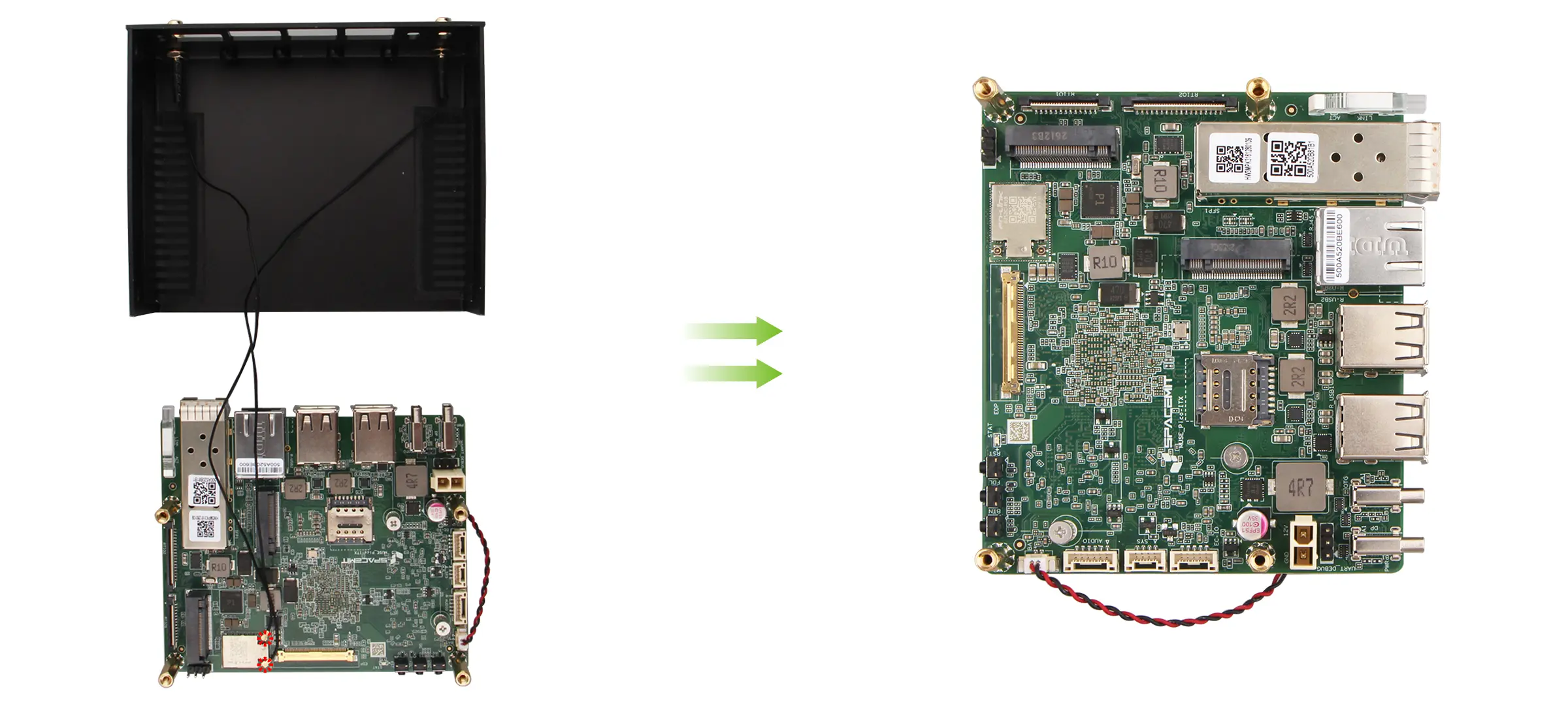
Metal Case Installation and Removal
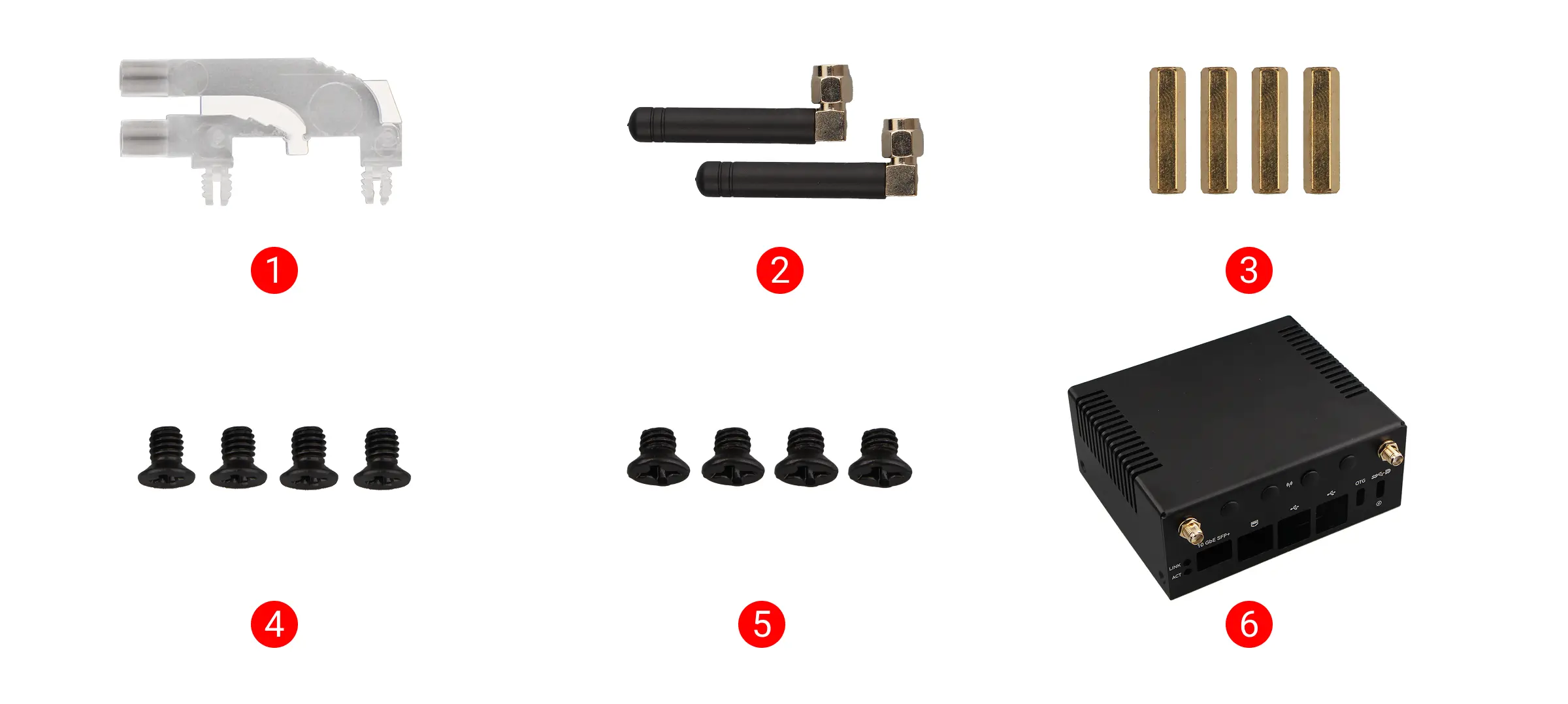
Parts List
-
①: 1x Light guide pillar
-
②: 2x Whip antennas
-
③: 4x KM3 * 4 mm screws
-
④: 4x KM2.5 * 4 mm screws
-
⑤: 4x M2.5 * 18 mm standoffs
-
⑥: 1x Metal case
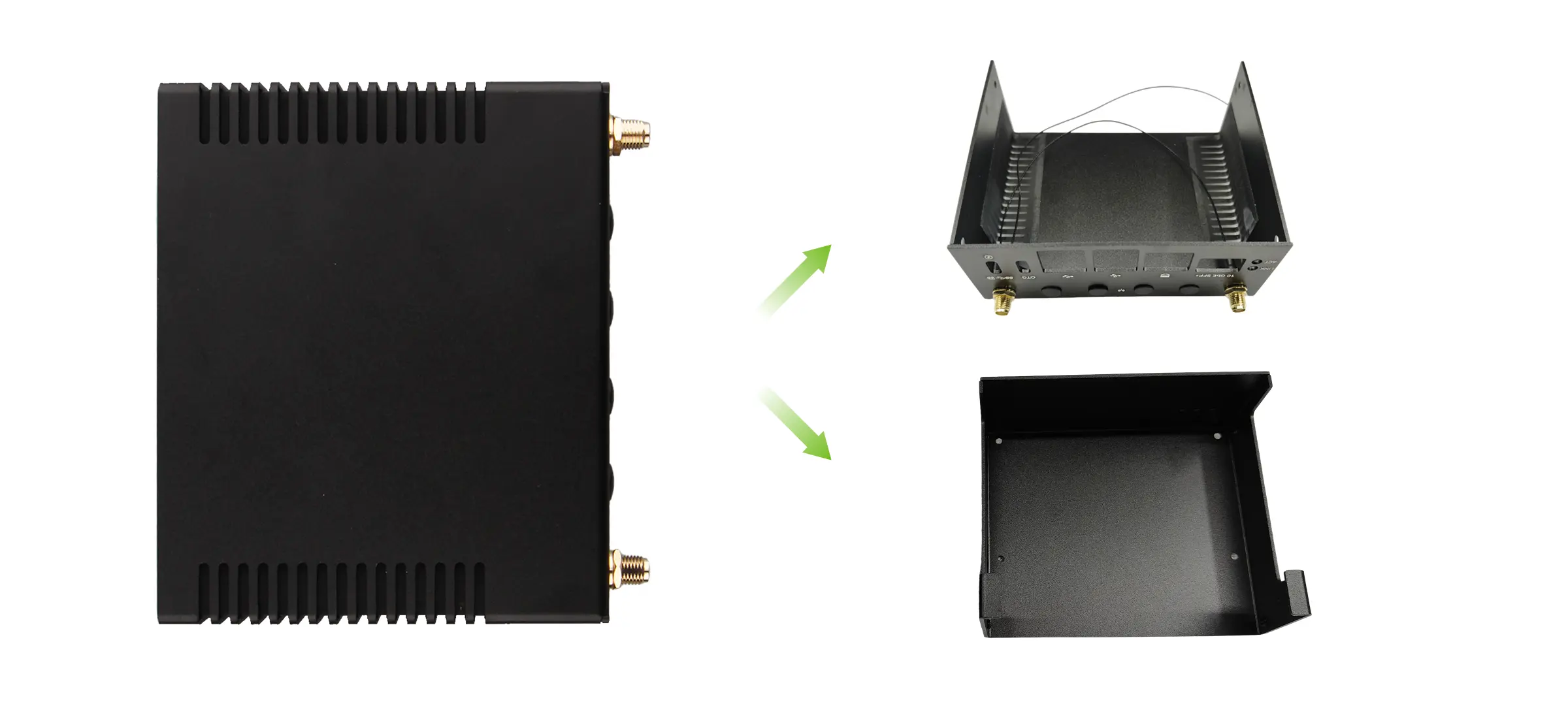
The metal case includes a metal top cover, a metal bottom cover, 2 SMA pigtail cables, a dust filter, and 4 button plugs. To disassemble or separate the metal case, slide the bottom cover outward.
Installing the Metal Case
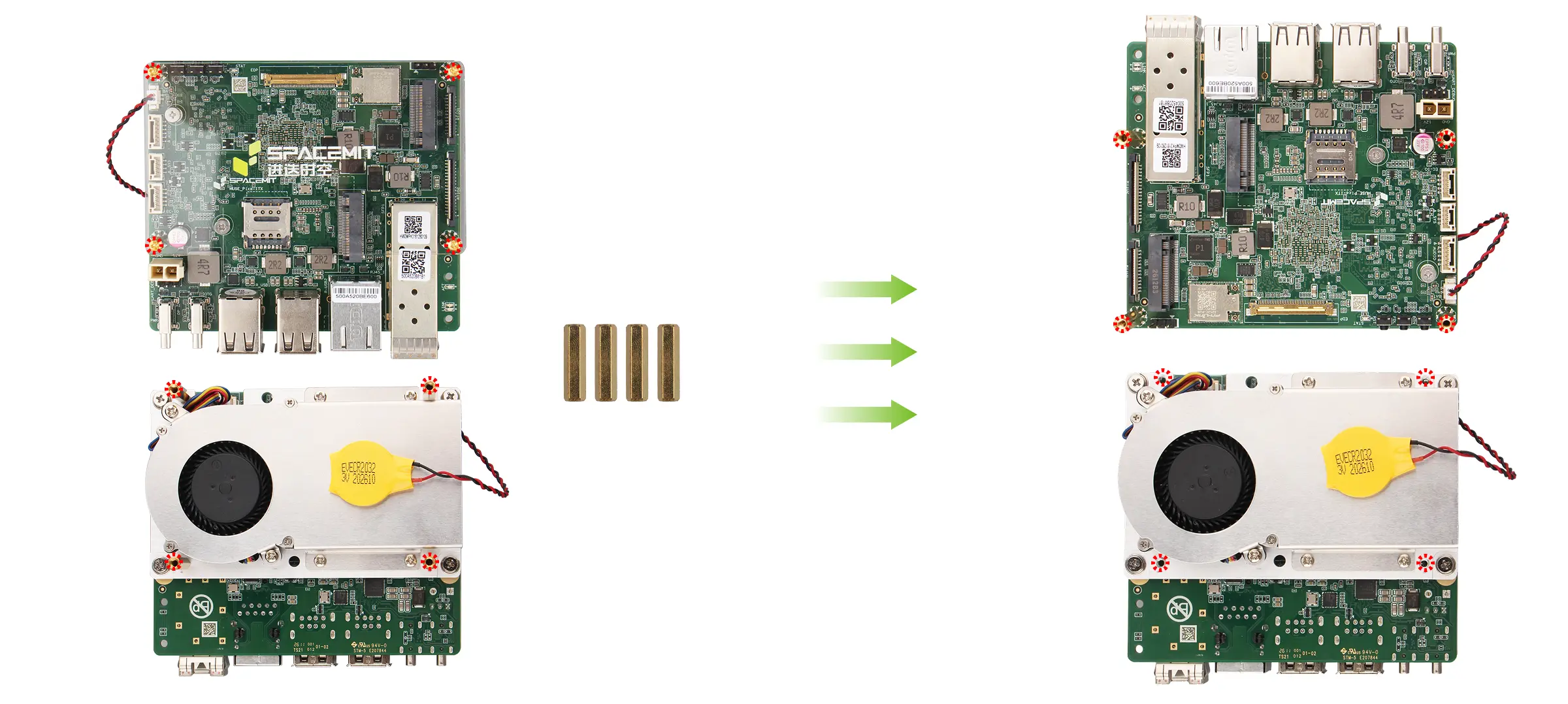
Removing the Transparent Acrylic Top Plate
For Milk-V Jupiter2 units that are not pre-installed with the metal case, you first need to remove the pre-installed transparent acrylic top plate and its mounting standoffs from the board, then replace the standoffs on the front side of the board with the 4 M2.5 * 18 mm standoffs that come with the metal case.
At the same time, please remove the raised standoffs from the heatsink on the back of the board to avoid interfering with the metal case installation.
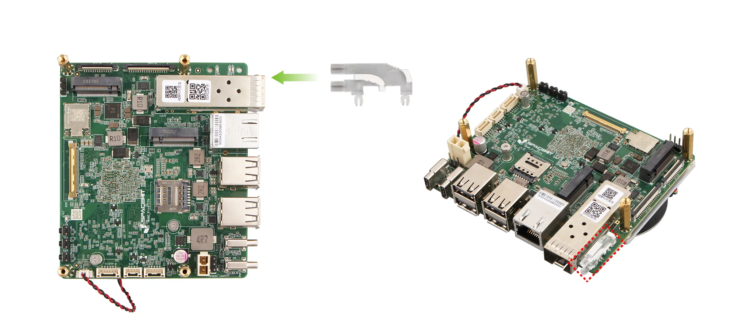
Installing the Light Guide Pillar
Install the light guide pillar to the corresponding position on the board and confirm that it is firmly seated.
Connecting the SMA Pigtail Cables
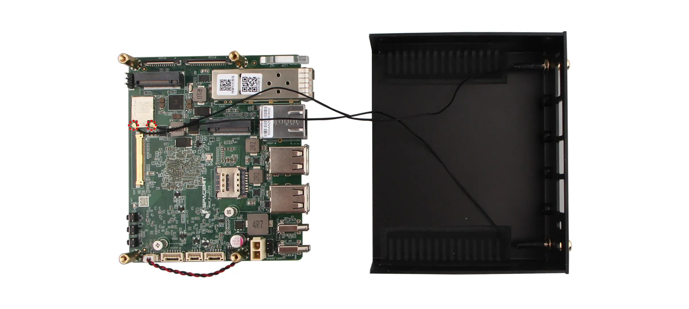
Connect the 2 SMA pigtail cables from the metal bottom cover to the antenna connectors on the board.
When connecting, gently press the connector to ensure the pigtail is latched in place to prevent it from loosening during subsequent installation steps.
Installing the Metal Top Cover
Slide the board into the corresponding position on the metal top cover, then secure the board to the top cover with 4 KM2.5 * 4 mm screws.
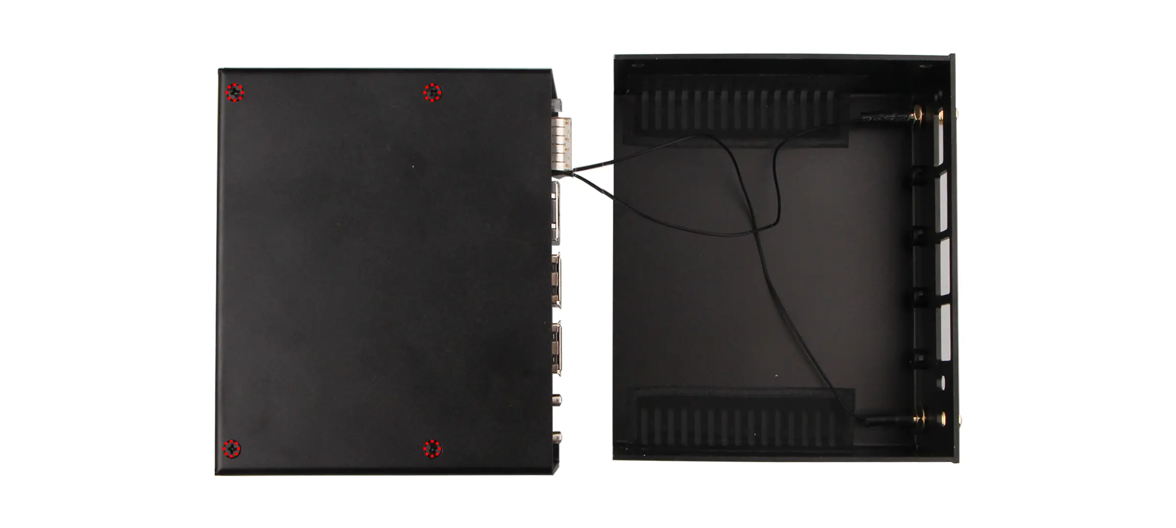
Installing the Metal Bottom Cover
Align the edges of the metal top cover with the metal bottom cover, then slowly slide the bottom cover into place.
Please note the following during installation:
-
Ensure that the board's connectors are aligned with the cutouts on the bottom cover;
-
Ensure that the SMA pigtail cables sit in the connector slot and are not pinched by the case;
-
Do not use excessive force when sliding in the cover, to avoid damaging the connectors or cables.
Once the position is confirmed to be correct, secure the top cover and bottom cover together with 4 KM3 * 4 mm screws.
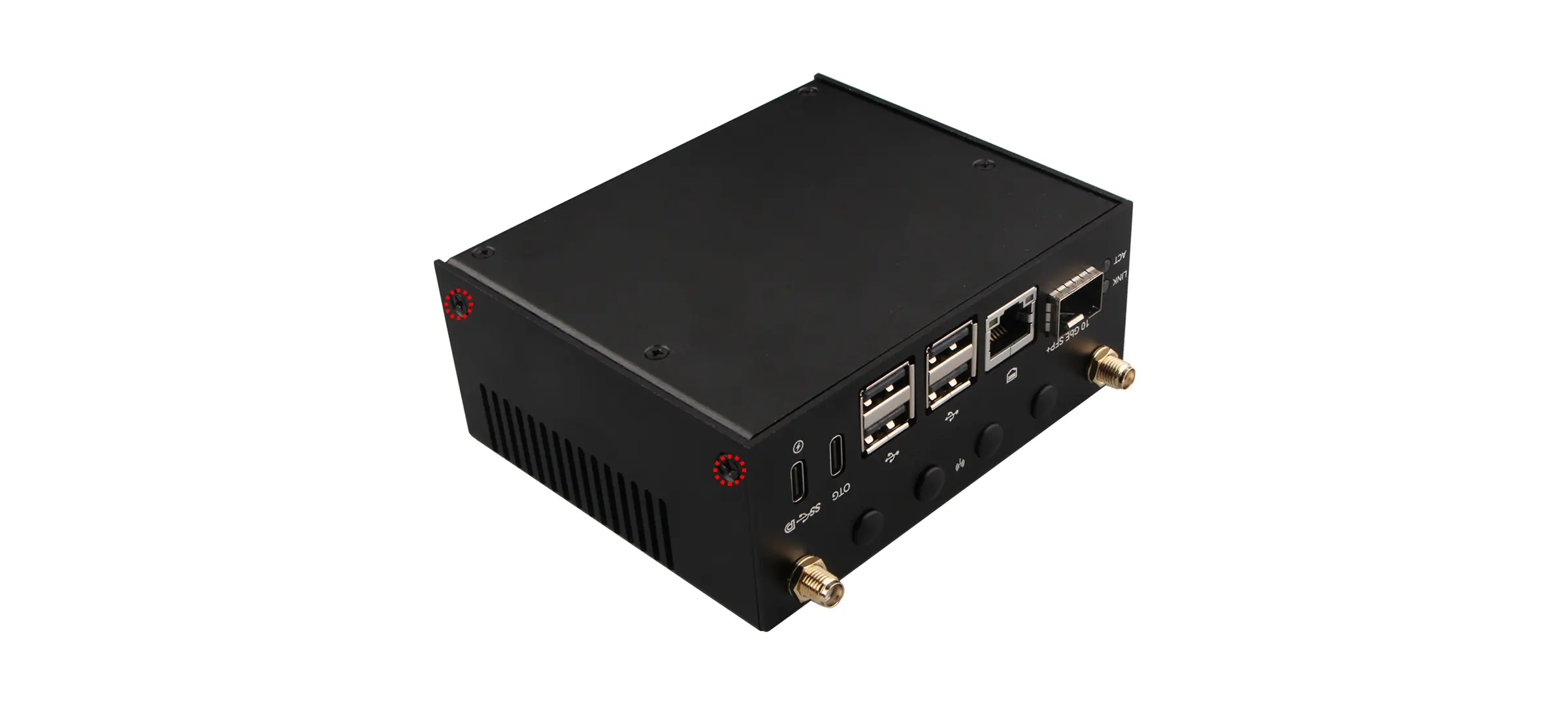
Installing the Whip Antennas
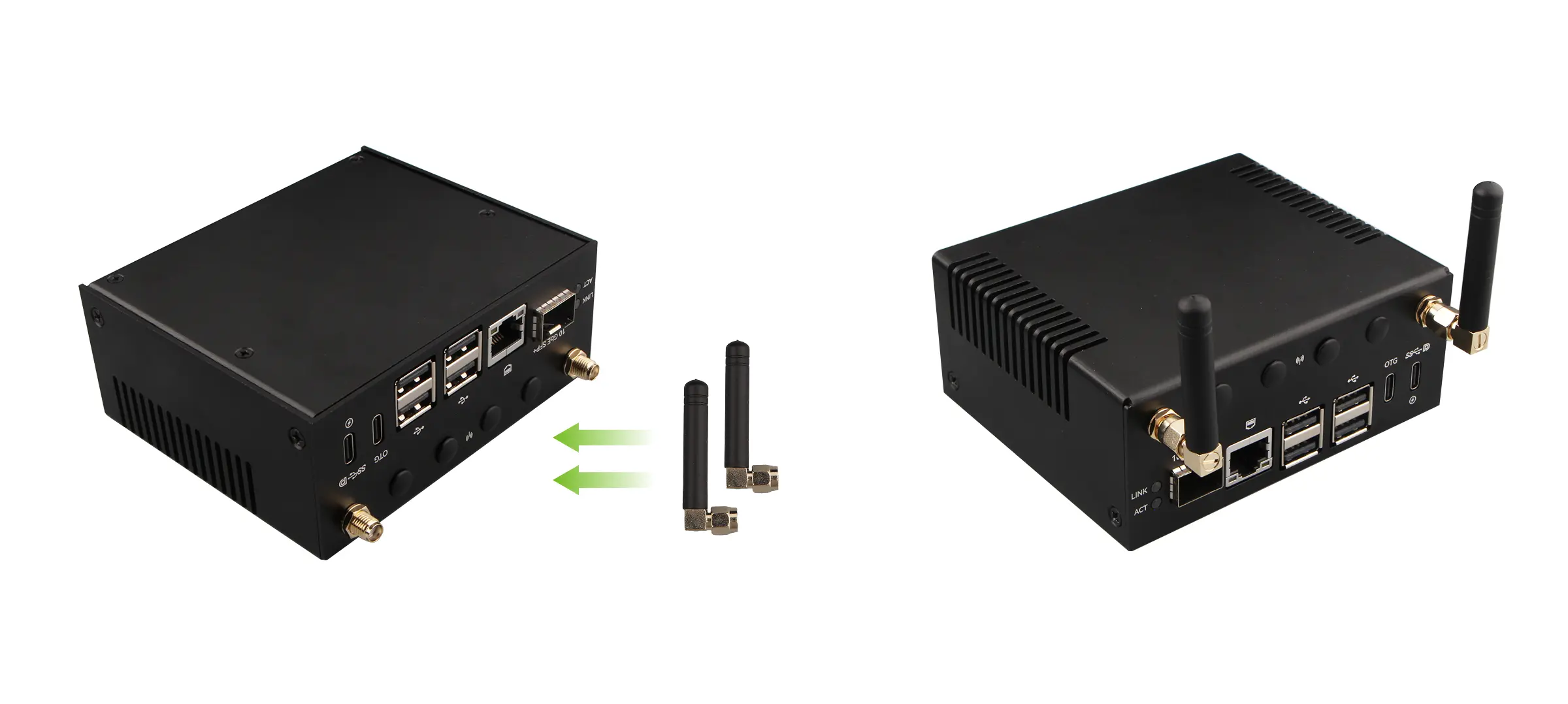
Install the 2 whip antennas onto the SMA connectors on the metal case and tighten them to secure.
Removing the Metal Case
Removing the Whip Antennas
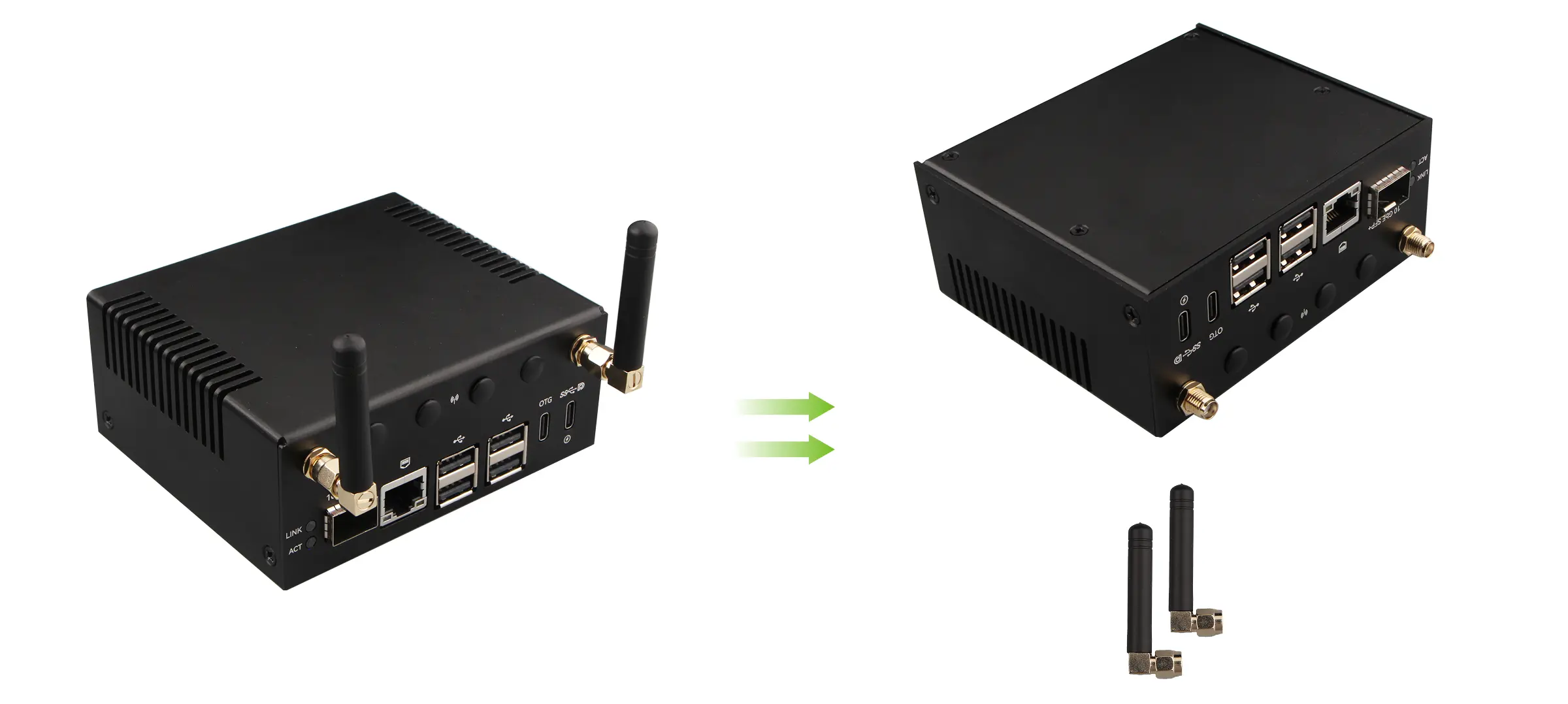
Unscrew and remove the 2 whip antennas from the SMA connectors.
Separating the Metal Top Cover and Bottom Cover
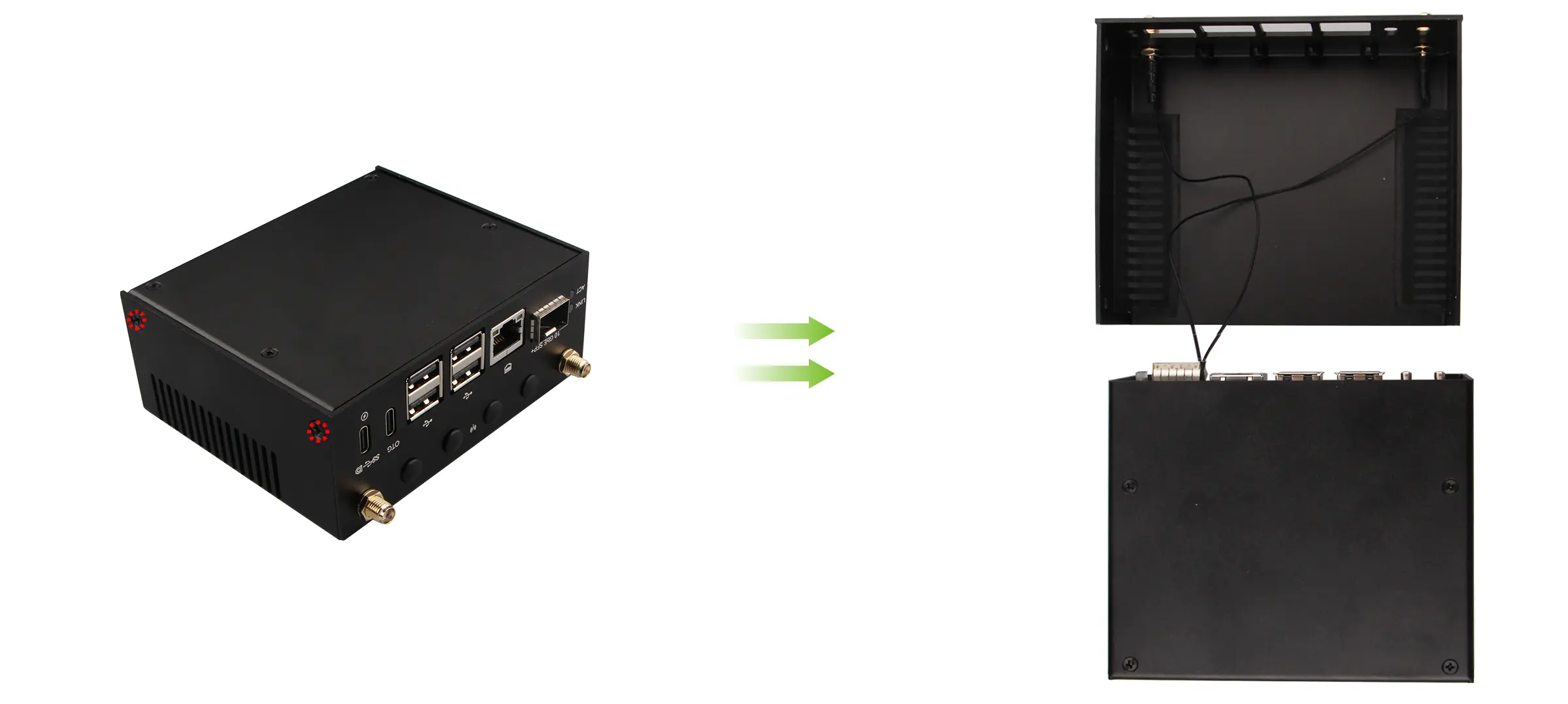
Remove the 4 KM3 × 4 mm screws securing the metal top cover and bottom cover together.
Then hold the top cover in place and slowly slide the bottom cover outward.
Removing the Board
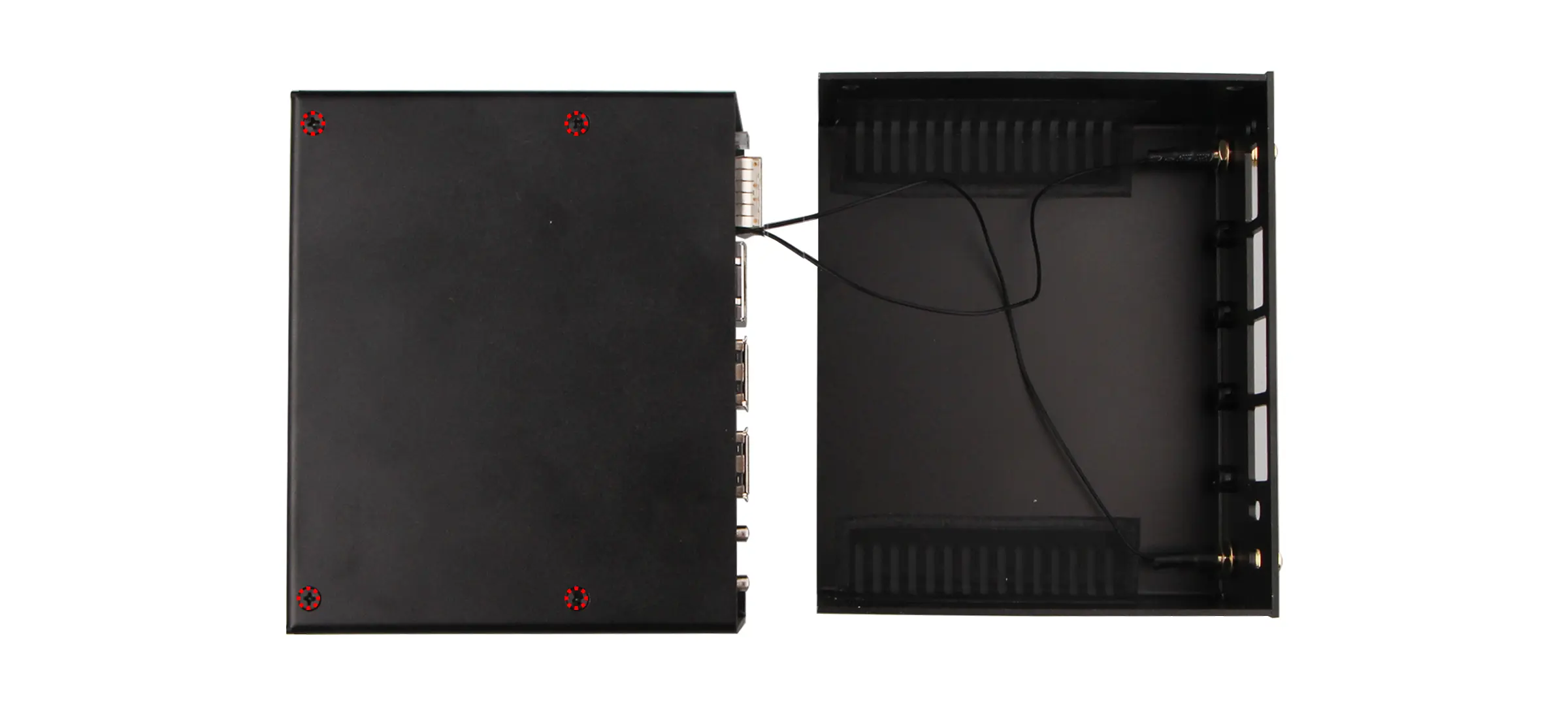
Remove the 4 KM2.5 × 4 mm screws securing the board to the metal top cover, then slowly slide the board out of the top cover.
Disconnecting the Antennas
Disconnect the 2 SMA pigtail cables from the antenna connectors on the board.
When disconnecting, gently lift the connector end of the pigtail at the connector rather than pulling on the cable.