Hardware Interface
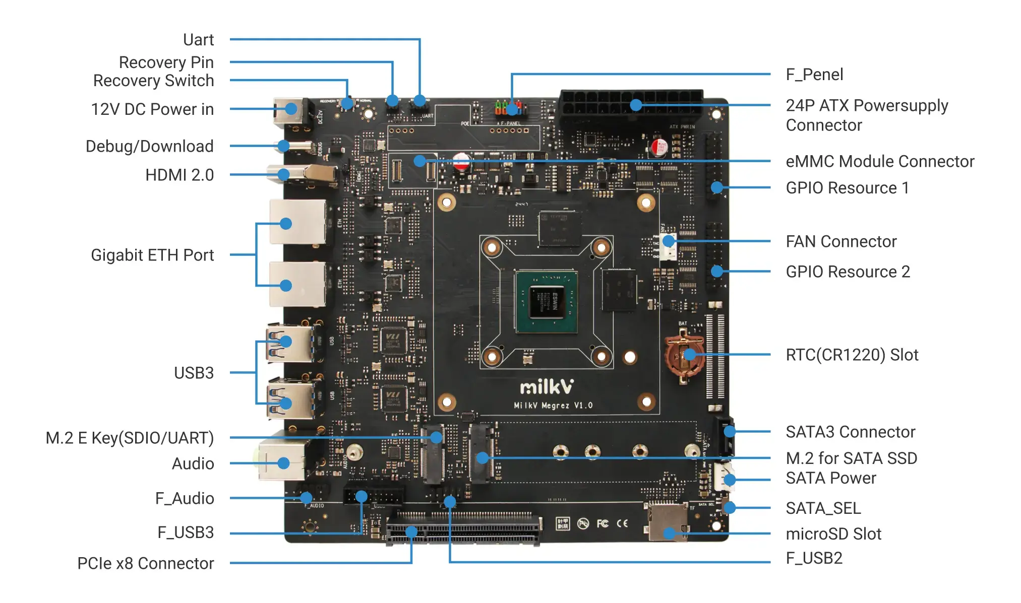
Power Interface
The Megrez motherboard supports the following power supply methods:
- DC interface, specification: 5.5*2.5mm, 12V/3A or higher.
- PC standard ATX 24-pin power supply.
- PoE power supply via network port (requires an additional PoE module).
The power consumption of the Megrez motherboard depends on the power and number of connected peripherals. Choose the appropriate power supply method based on specific requirements.
Type-C Interface
- The Type-C interface can be used for flashing or debugging. It allows the installation of system images to the board's
SPI FLASH,eMMC module, orSATA SSD.
F_PANEL Interface
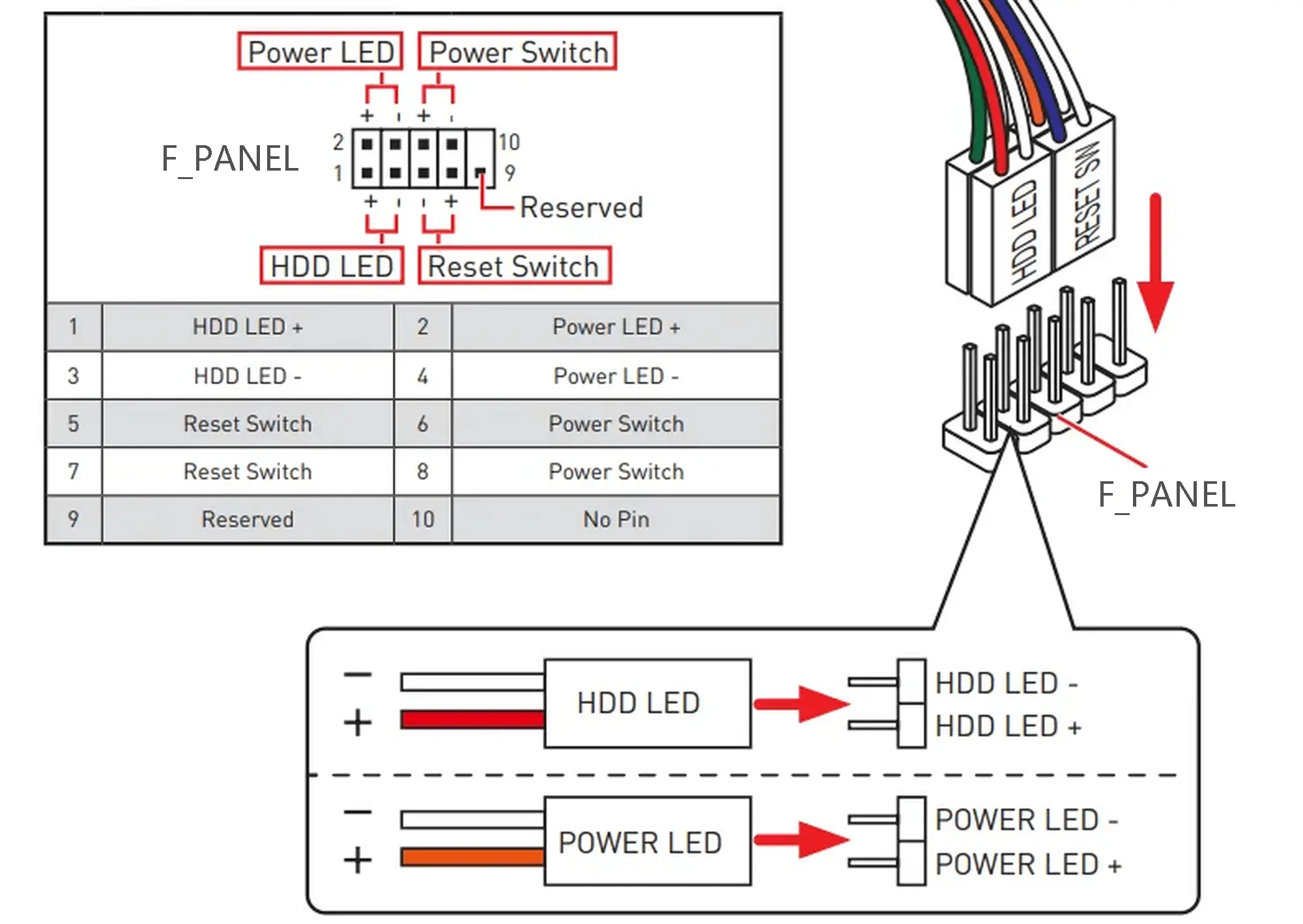
F_PANEL stands for Front Panel and is a set of pins used to connect the front panel of a standard PC case. It includes signals for power button, reset button, power indicator, and hard drive activity light.
After powering the Megrez motherboard using one of the methods mentioned in the Power Interface section, the board will automatically boot. The power button in the F_PANEL is used for shutting down or turning the board back on after a shutdown.

F_AUDIO, F_USB2, F_USB3 Interfaces
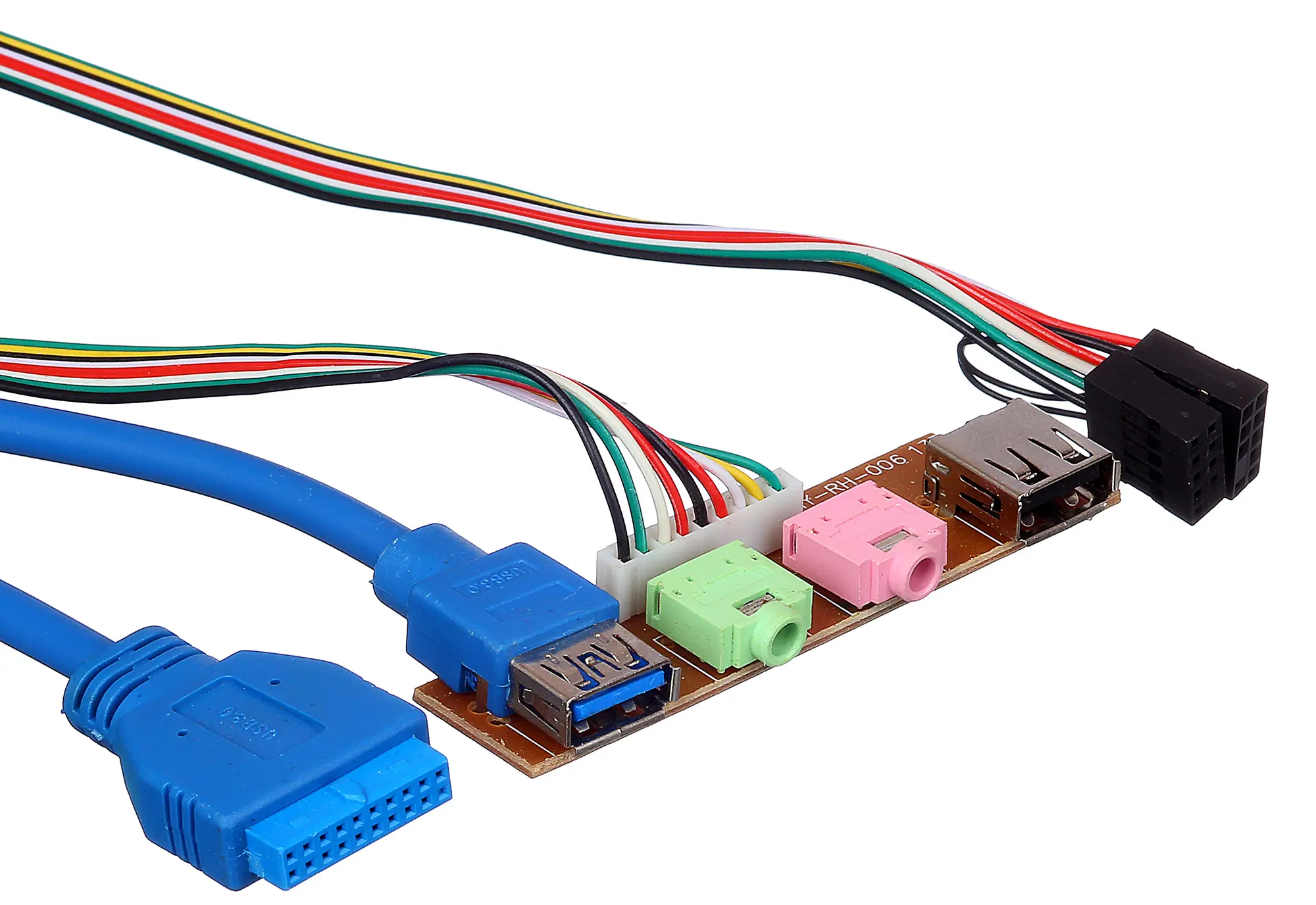
Below is an example of a standard PC case front panel USB and audio expansion board, which includes Audio, USB2.0, and USB3.0 interfaces. You can use the corresponding connectors on the Megrez motherboard to extend USB and audio interfaces to the front panel of the PC case.
The Megrez motherboard already has onboard Audio, USB2.0, and USB3.0 interfaces, so the corresponding functions can be used without a PC case.
F_AUDIO
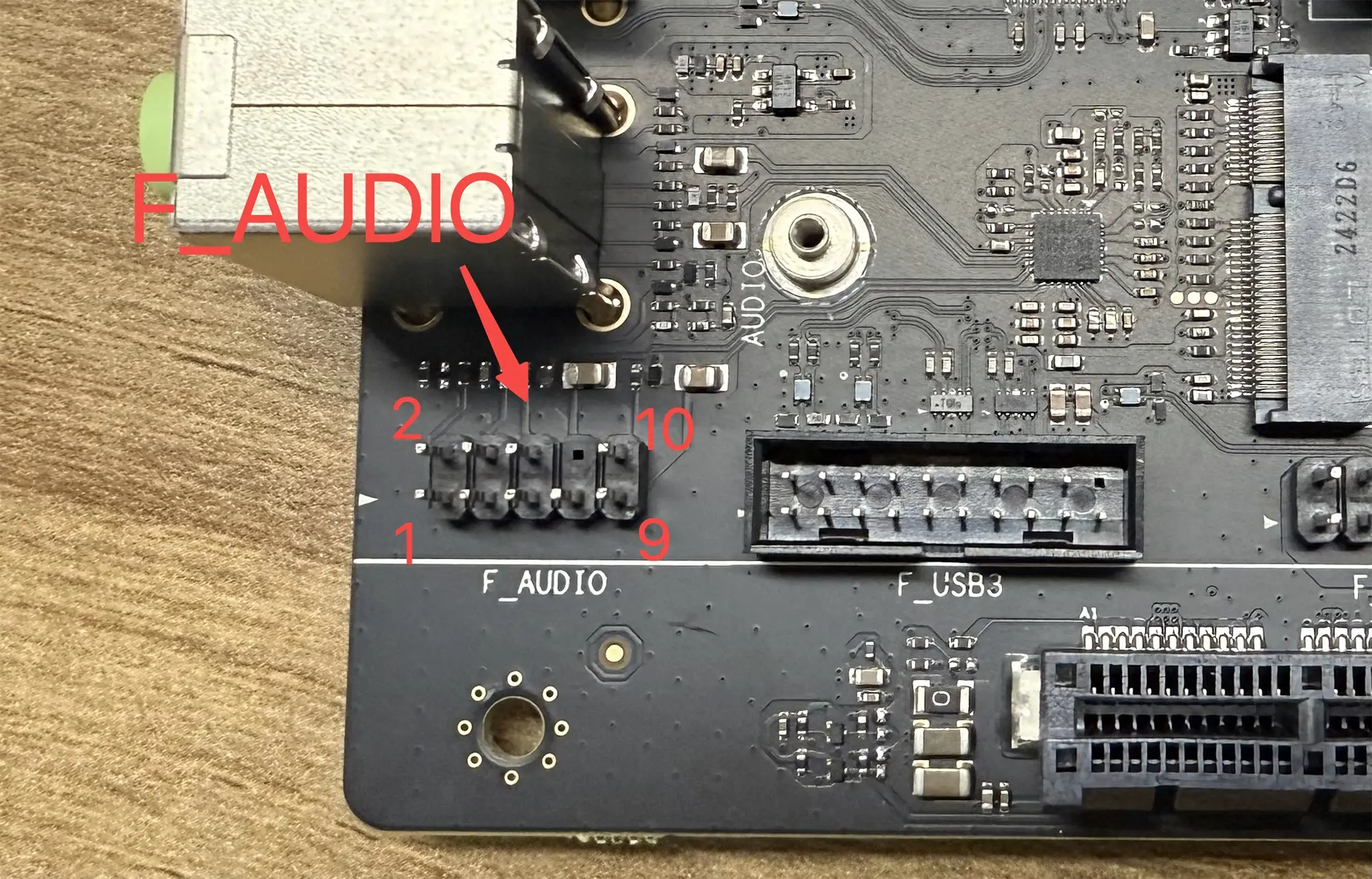
The F_AUDIO audio interface on the Megrez motherboard is compatible with the AC'97 front audio interface. The pin definitions are as follows:
| Description | PIN | PIN | Description |
|---|---|---|---|
| MIC_IN | 1 | 2 | GND |
| MIC_POWER | 3 | 4 | GND |
| AUDIO_OUT_R | 5 | 6 | RET_R(NC) |
| NC | 7 | ||
| AUDIO_OUT_L | 9 | 10 | RET_L(NC) |
F_USB2
The F_USB2 interface on the Megrez motherboard is compatible with standard PC motherboard USB2.0 interfaces. The pin definitions are as follows:
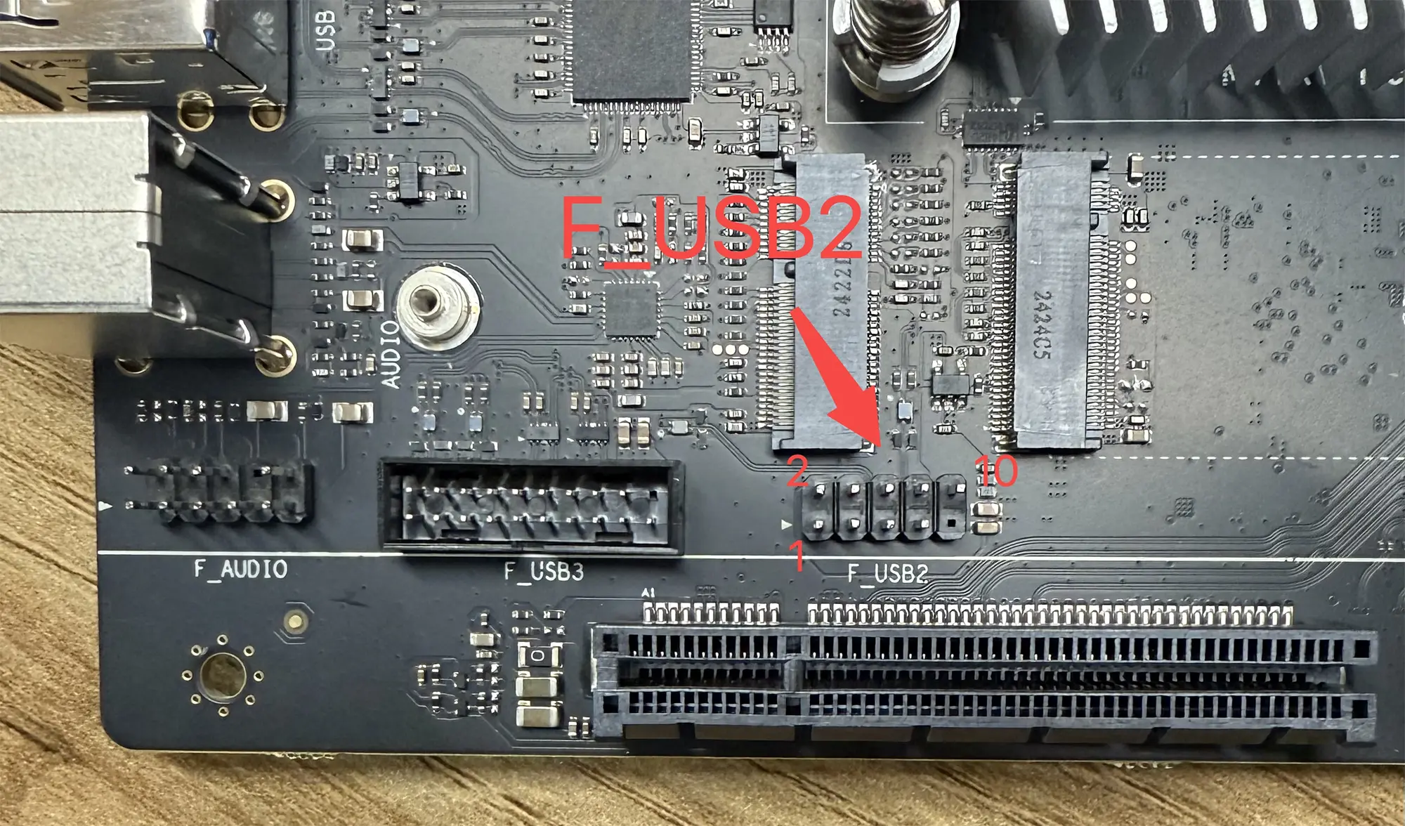
| Description | PIN | PIN | Description |
|---|---|---|---|
| 5V | 1 | 2 | 5V |
| USB1- | 3 | 4 | USB2- |
| USB1+ | 5 | 6 | USB2+ |
| GND | 7 | 8 | GND |
| 10 | GND |
F_USB3
The F_USB3 interface on the Megrez motherboard is compatible with standard PC motherboard USB3.0 interfaces. The pin definitions are as follows:
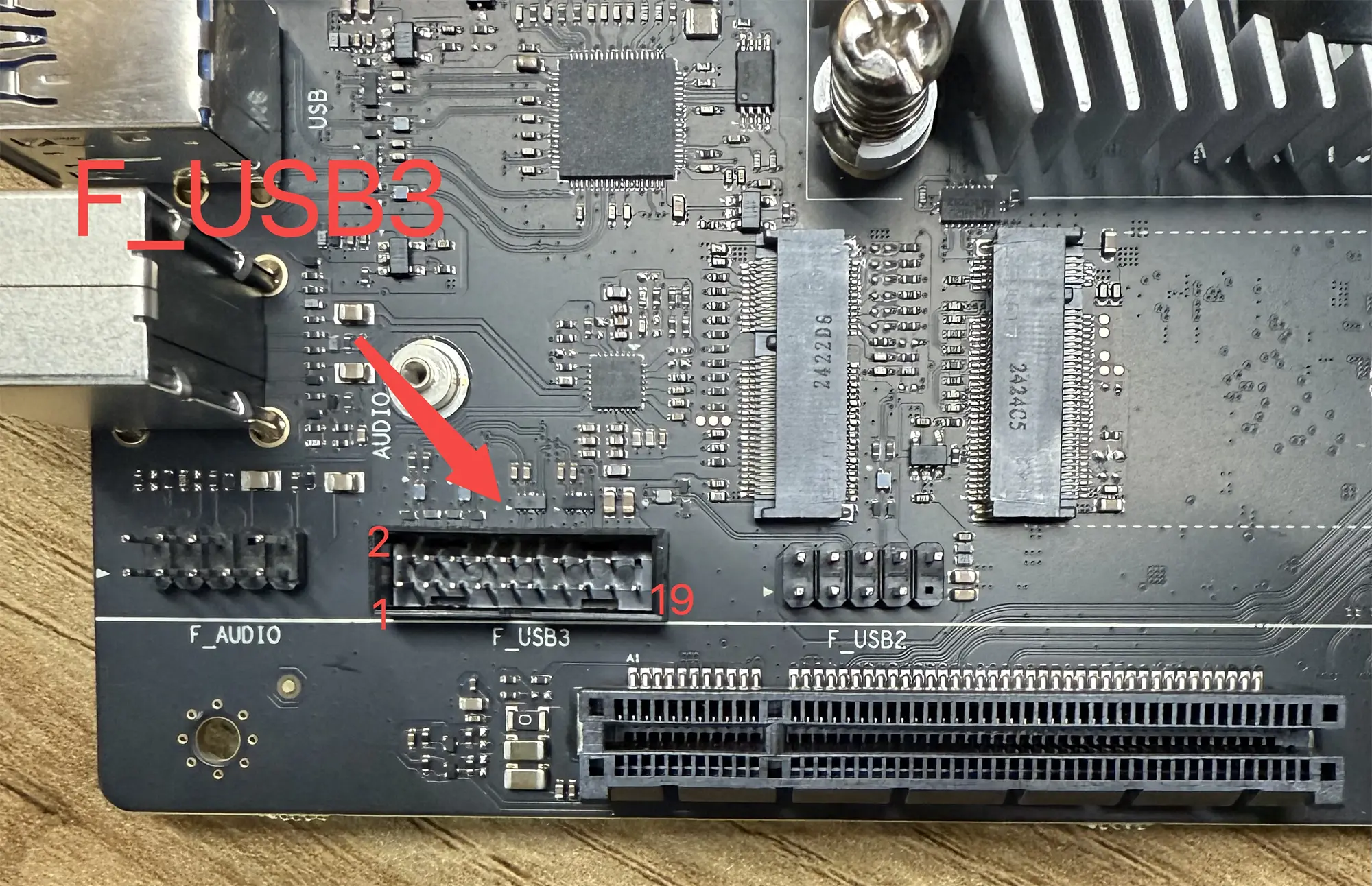
| Description | PIN | PIN | Description |
|---|---|---|---|
| ID | 1 | 2 | P2-D+ |
| P1-D+ | 3 | 4 | P2-D- |
| P1-D- | 5 | 6 | GND |
| GND | 7 | 8 | P2-SSTX+ |
| P1-SSTX+ | 9 | 10 | P2-SSTX- |
| P1-SSTX- | 11 | 12 | GND |
| GND | 13 | 14 | P2-SSRX+ |
| P1-SSRX+ | 15 | 16 | P2-SSRX- |
| P1-SSRX- | 17 | 18 | Vbus |
| Vbus | 19 |
Recovery/Normal Boot Toggle Switch
The default boot order for the Megrez motherboard is SPI Flash (U-boot) -> SD/eMMC/SATA.
If the U-boot firmware in the SPI Flash is damaged and cannot boot, you can use the Recovery/Normal Boot Toggle Switch to enter recovery mode. In this mode, the Megrez motherboard will load a temporary U-boot from USB.
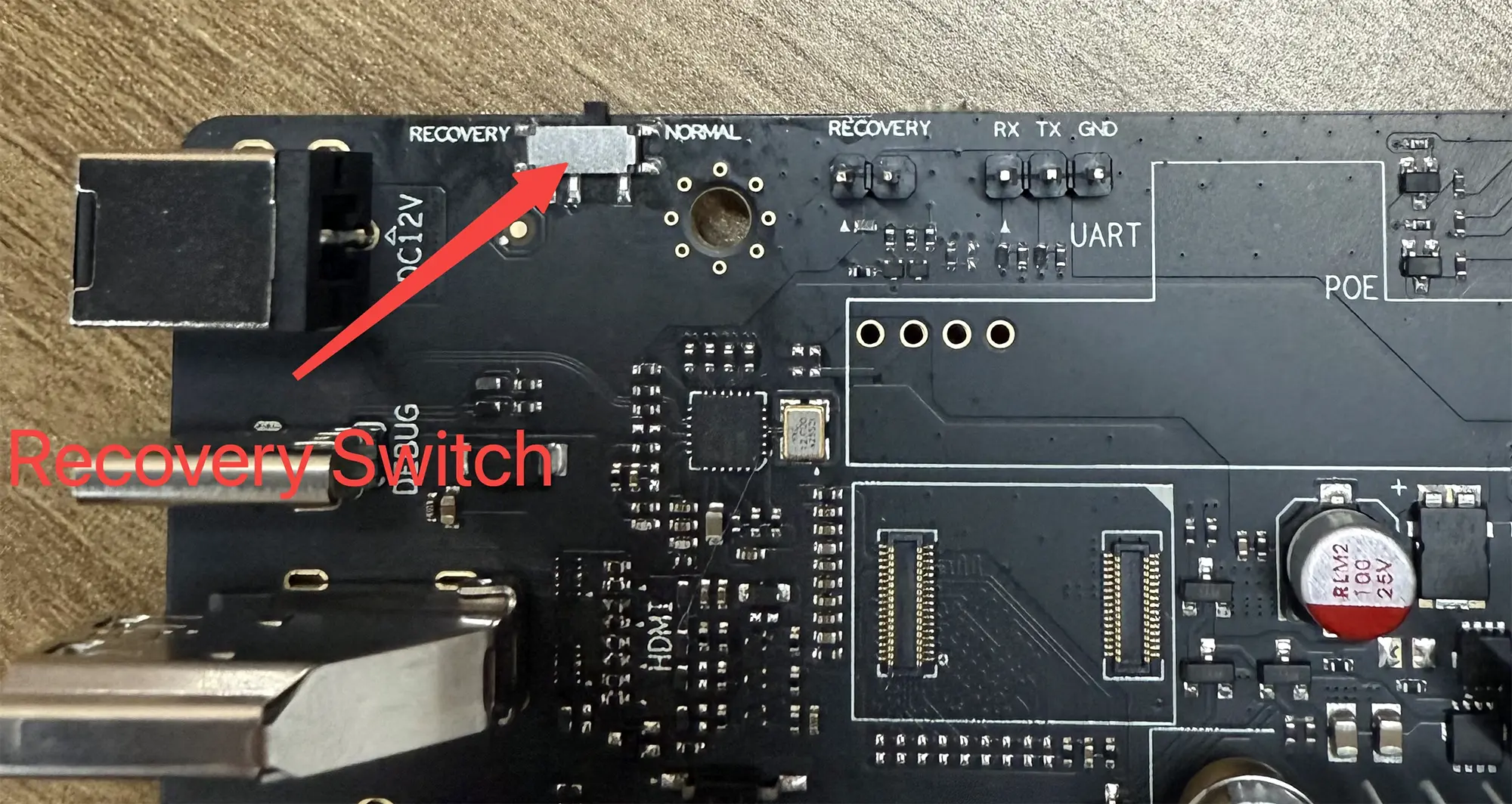
The status definitions are as follows:
| Description | PIN | PIN | Description |
|---|---|---|---|
| Boot from USB U-boot (Temporary) | RECOVERY | NORMAL | Boot from SPI Flash U-boot |
SATA SEL Toggle Switch
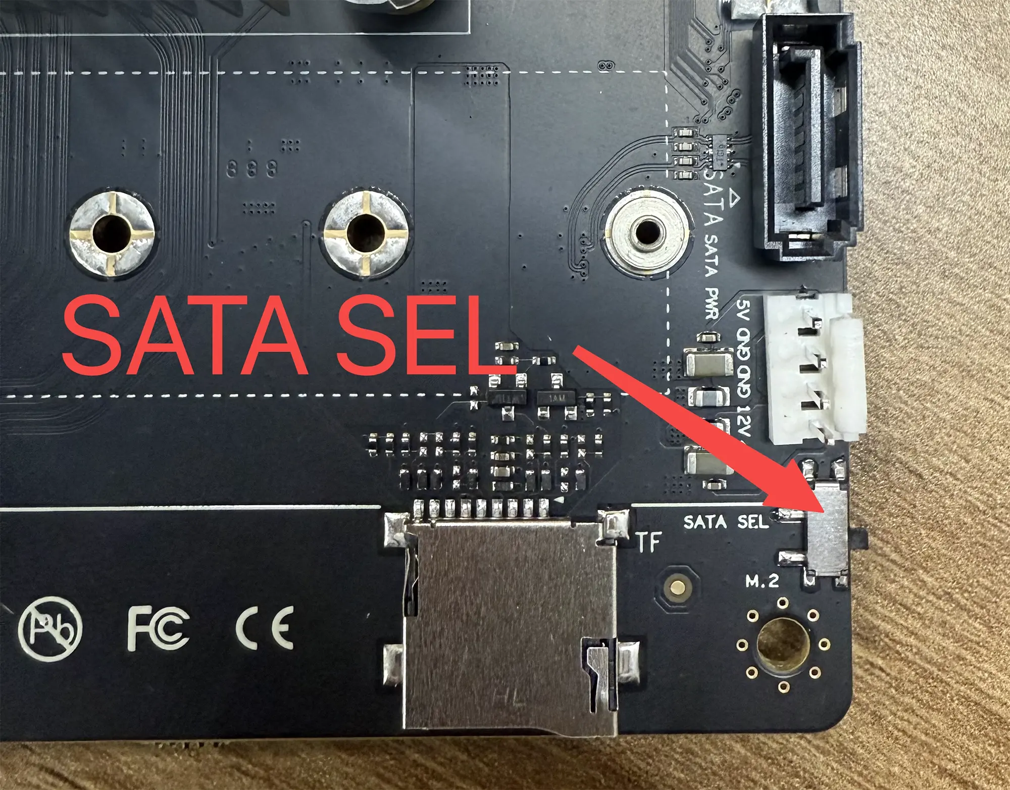
The Megrez motherboard has two SATA hard drive interfaces:
One is the M.2 SATA SSD interface, and the other is the SATA3 hard drive interface. These two interfaces share the same SATA signal and can be switched using the SATA SEL Toggle Switch.
Debug/Download
The Megrez motherboard has a built-in CH340 chip. By default, connecting the Type-C port to a PC enables debugging, and a new device tty.usbserial-1220 will appear on the PC.
The default serial port parameters for the Megrez motherboard are as follows:
baudrate: 115200
data bit: 8
stop bit: 1
parity  : none
flow control: none
