Hardware Interface
Power interfaces
Titan support the following two power supply methods:
- PC standard ATX 24-pin power supply
- DC power supply, 5.5*2.5mm
If both ATX and DC power supplies are present, ATX power will be used first.
The power consumption of a Titan motherboard depends on the power and number of connected peripherals, requiring the selection of an appropriate power supply method based on specific circumstances. The following power consumption figures are for reference only, based on idle and CPU stress testing conditions under normal system operation. If you have connected other peripherals, such as an external graphics card, you also need to consider the graphics card's power consumption.
- DDR4 64GB(32GB*2) + M.2 NVMe SSD(128G), Idle power ~14W (12V/1.2A)
- DDR4 64GB(32GB*2) + M.2 NVMe SSD(128G), Full load power ~30W (12V/2.5A)
DDR4 DIMM Slot
The Titan motherboard has two DDR4 slots and supports DDR4 UDIMM modules. It supports both single-module and dual-module configurations. For dual-module configurations, using two modules with matching specifications is recommended for best compatibility. For a list of currently verified DDR4 modules, please refer to the following link:
PCIe M Key
The PCIe M Key interface is an interface standard used to connect high-performance expansion devices. It is one of the physical interface forms of the PCI Express (PCIe) bus.
The Titan's onboard PCIe M Key interface supports PCIe Gen4 x4 and is primarily used for installing NVMe M.2 SSDs as the system boot medium. Supported sizes include 2230/2242/2260/2280.
PCIe x16 Slot
Onboard full-size PCIe x16 slot, supporting PCIe Gen4 x16, compatible with high-performance graphics cards.
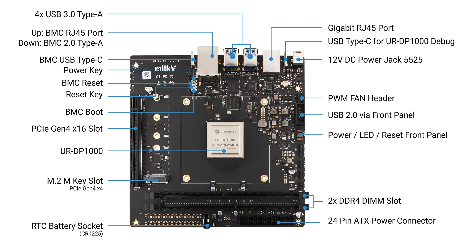
Gigabit Ethernet Port
Onboard dual Gigabit RJ45 Ethernet port, supporting 10/100/1000 Mbps auto-negotiation.
Fan Connector
Onboard standard ATX 4-Pin fan connector with PWM control support.
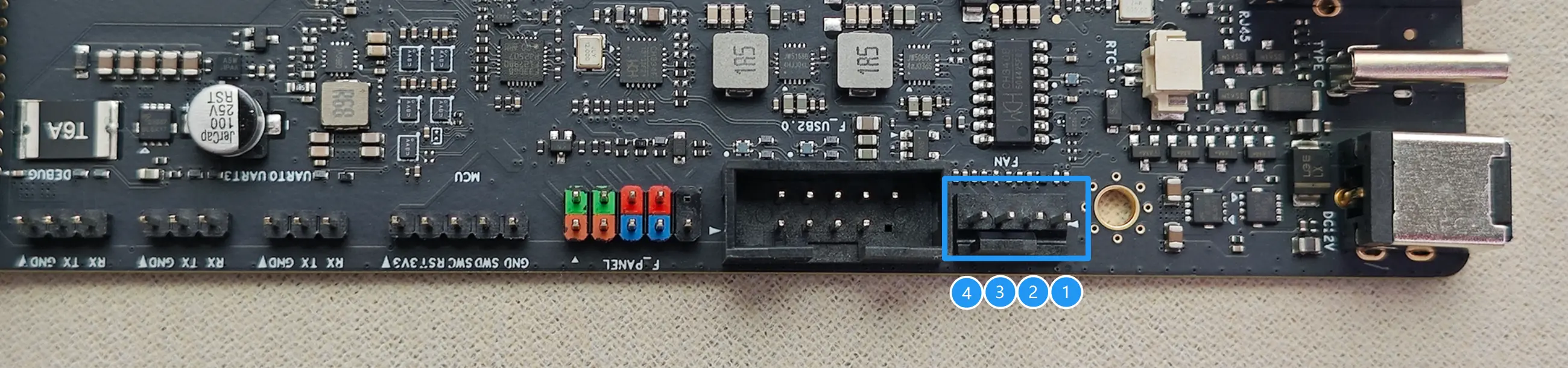
| PIN | NAME | Description |
|---|---|---|
| 1 | PWM | PWM Control Signal |
| 2 | TACH | Tachometer Signal |
| 3 | VCC-12V | Power (12V) |
| 4 | GND | Ground |
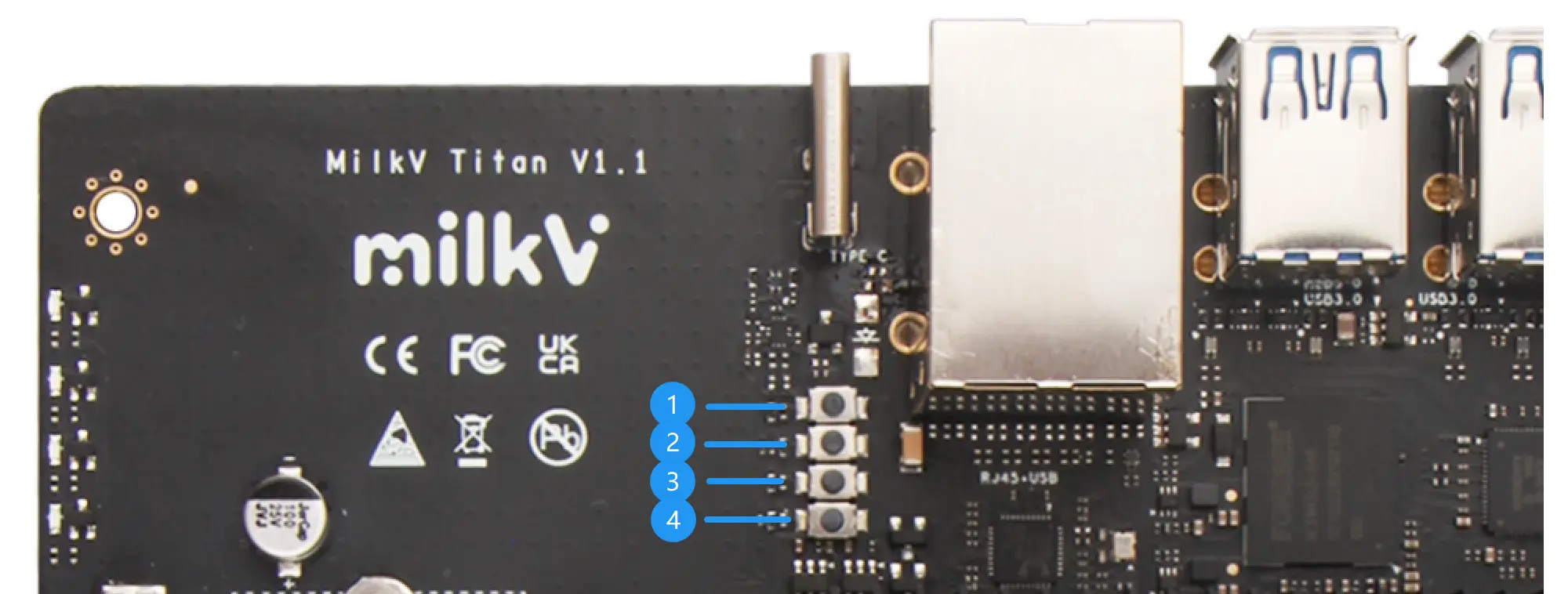
Power LEDs
When using an ATX power supply, the red LED at position 1 will remain constantly lit. The three blue LEDs (2, 3, and 4) currently do not have a distinguishing function; they will all remain constantly lit when the motherboard is working normally.
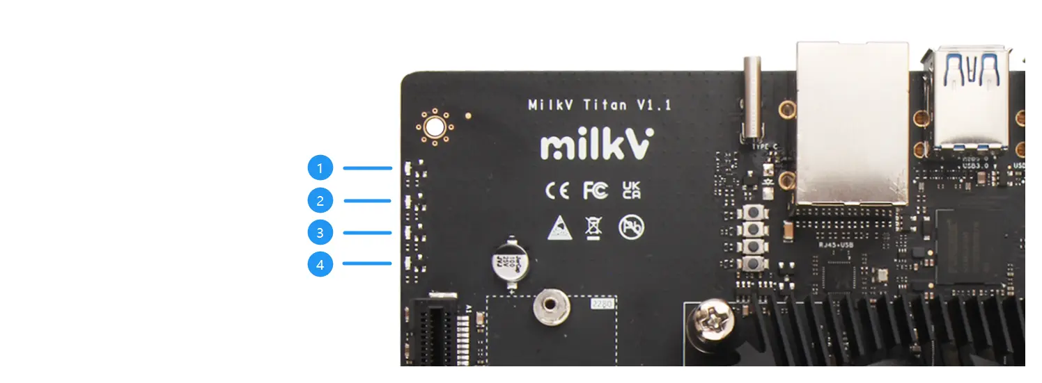
You can also use the F_PANEL interface to extend the power indicator LED, which is a standard PC chassis front panel expansion interface.
Onboard buttons
- Motherboard power button. Press and hold for 3 seconds to force power off. You can also use the F_PANEL interface to extend the power button; both have the same function.
- The BMC reset button allows you to manually reset the BMC module.
- The motherboard reset button allows you to manually reset the motherboard power. You can also use the F_PANEL interface to extend the reset button; both have the same function.
- BMC Boot Button: Press and hold this button while powering on the BMC to put it into burning mode.
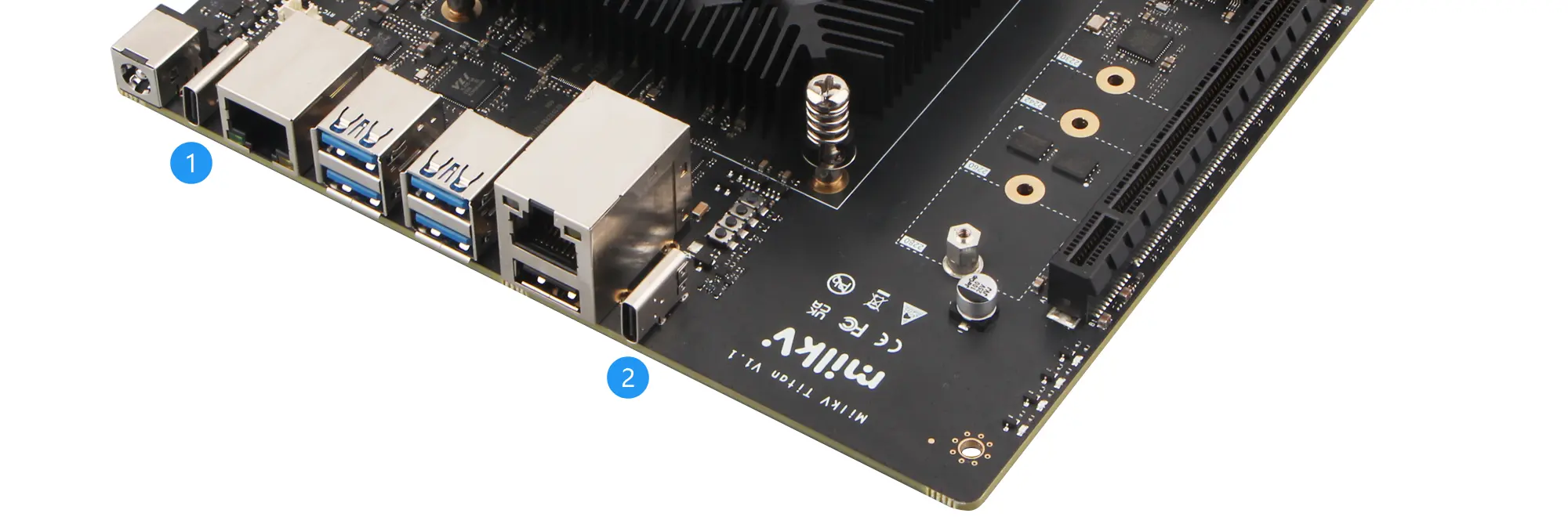
Type-C Interfaces
The Titan motherboard has two Type-C ports:
-
The Type-C port near the DC power connector is the UR-DP1000's debugging port. An onboard USB-to-UART module connects to the UR-DP1000. For detailed usage instructions, please refer to: USB Type-C Debug Port Guide
-
The other Type-C port is the programming port for the BMC module. Please refer to: BMC Usage
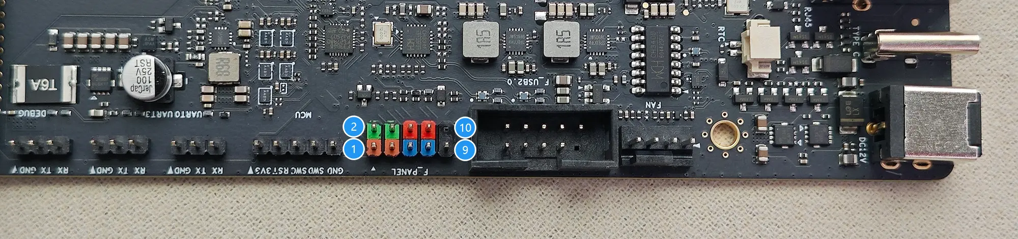
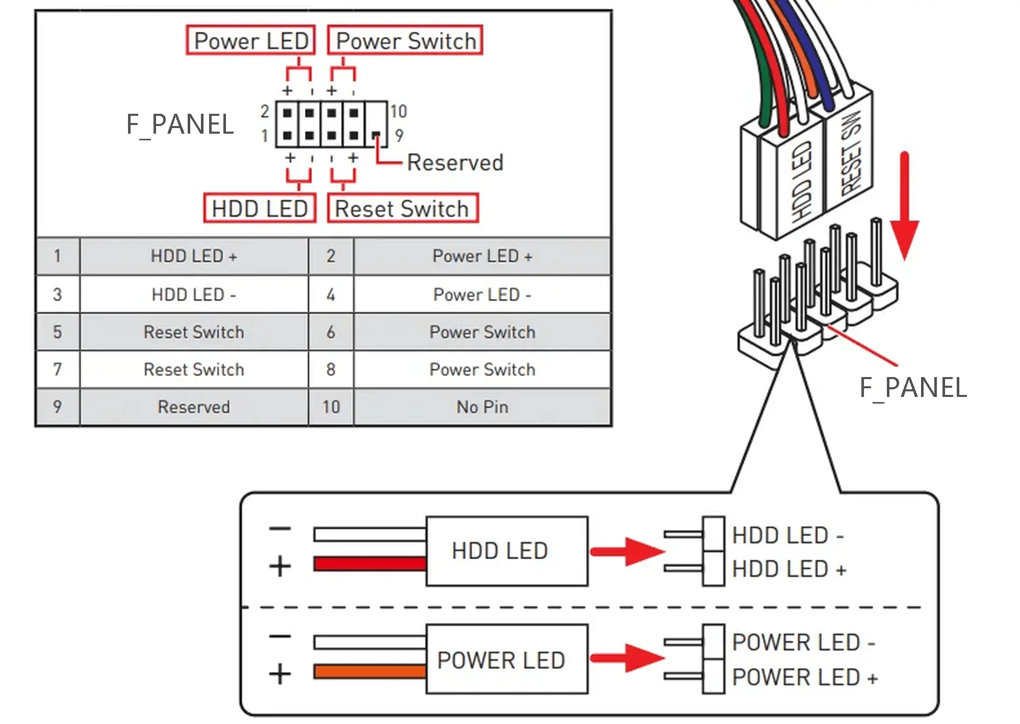
F_PANEL Interface
F_PANEL is the abbreviation of Front Panel, which is a set of jumpers used to connect the front panel of a standard PC case. It includes four groups of signals: the power button, the reset button, the power indicator LED, and the HDD LED.
F_USB2.0 Interface
The F_USB2.0 port on the Titan motherboard is compatible with standard PC motherboard USB2.0 ports. You can use this port to extend two USB2.0 ports onto the front panel of your PC case. The pin definitions are as follows:
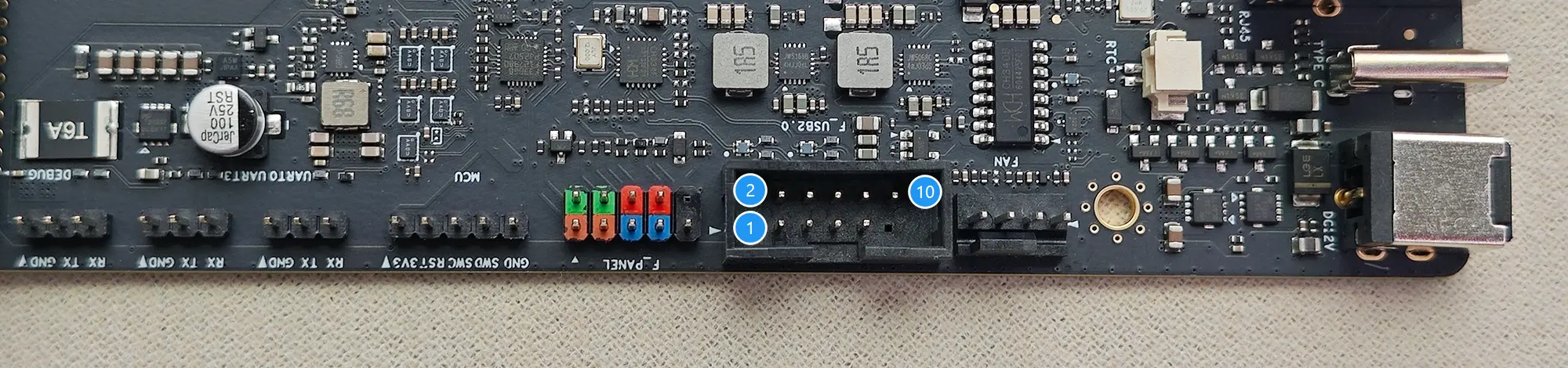
| Description | PIN | PIN | Description |
|---|---|---|---|
| 5V | 1 | 2 | 5V |
| USB1- | 3 | 4 | USB2- |
| USB1+ | 5 | 6 | USB2+ |
| GND | 7 | 8 | GND |
| 10 | GND |
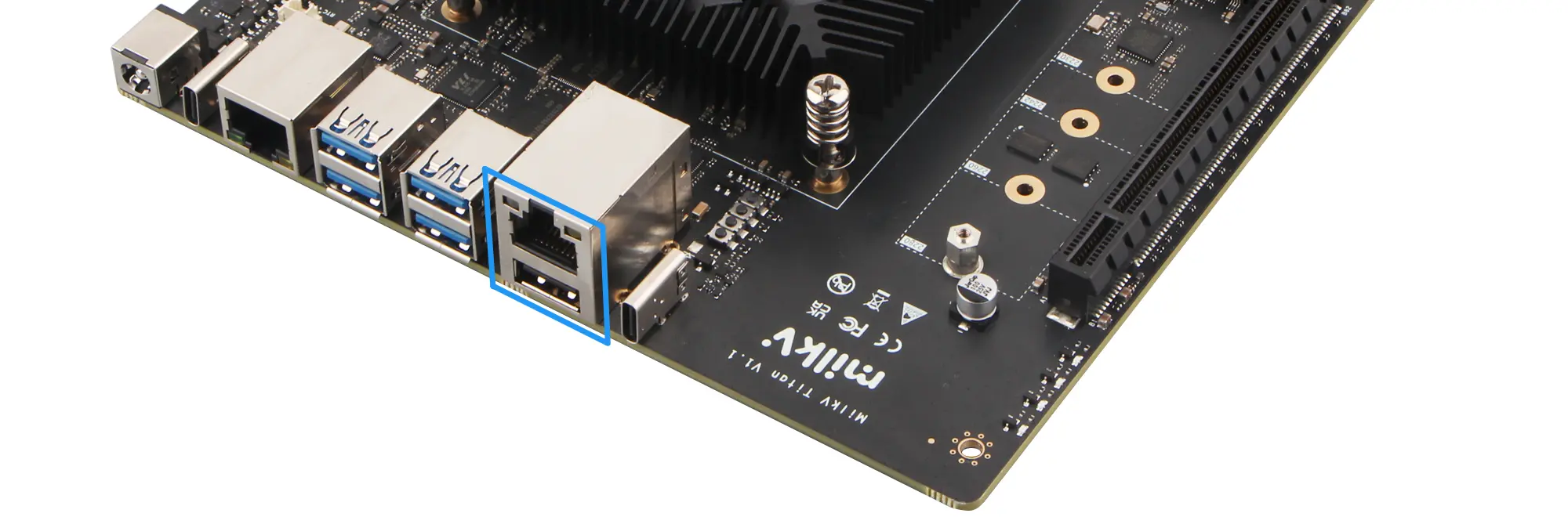
BMC Ethernet and USB2.0
The BMC module comes with an RJ45 network port and a USB 2.0 interface. For detailed usage instructions, please refer to: BMC Usage