Hardware Interface
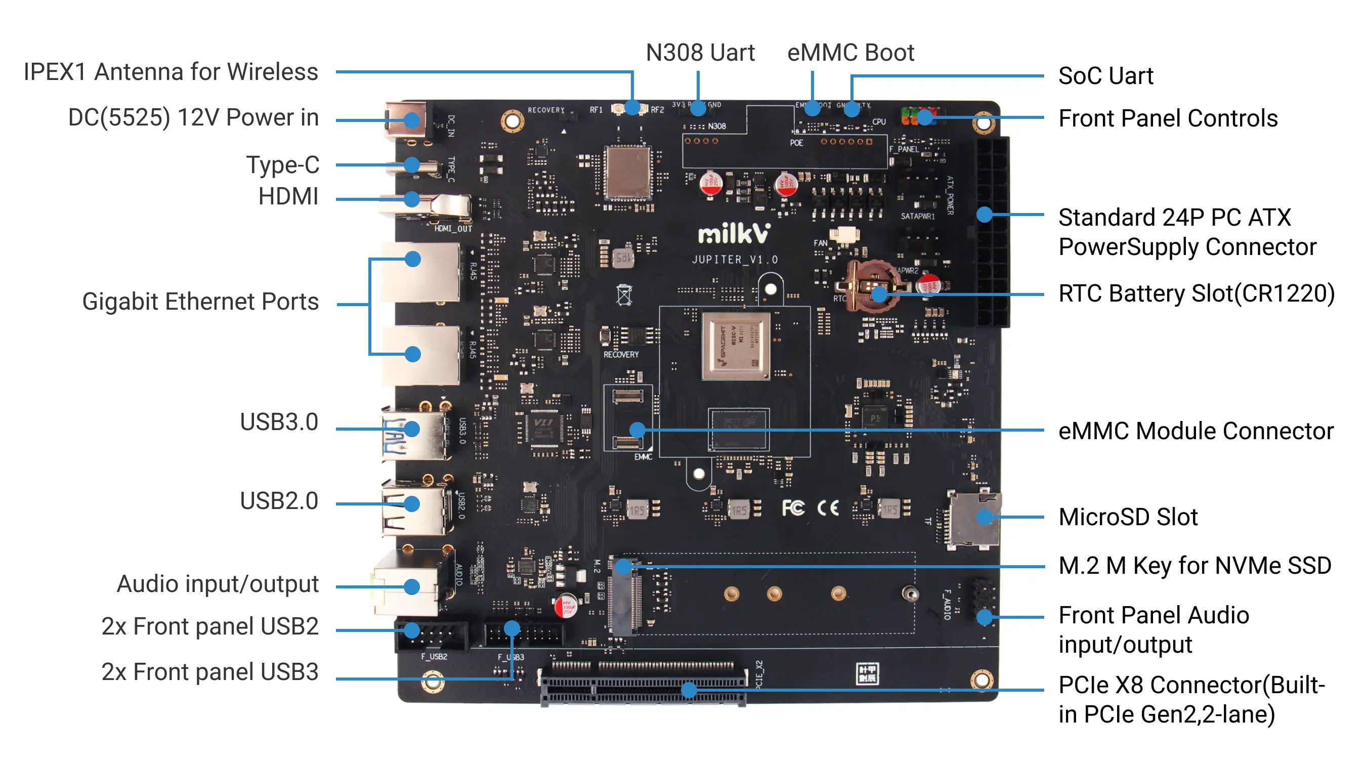
Power interfaces
Jupiter supports the following power supply modes:
- DC power supply, 5.5*2.5mm, 12V/3A or above
- Type-C PD Power Adapter
- PC standard ATX 24-pin power supply
- Ethernet port PoE power supply (requires additional PoE module)
The power consumption of the Jupiter board depends on the power and number of connected peripherals. You need to choose the appropriate power supply method according to the specific situation.
Power indicator
There is a blue LED near the ATX power supply interface. This LED will light up only when the ATX power supply is used. When using other power supply methods, there is no power indicator light on the Jupiter motherboard. You need to connect an HDMI monitor or check the serial port log to determine whether the system has started normally.
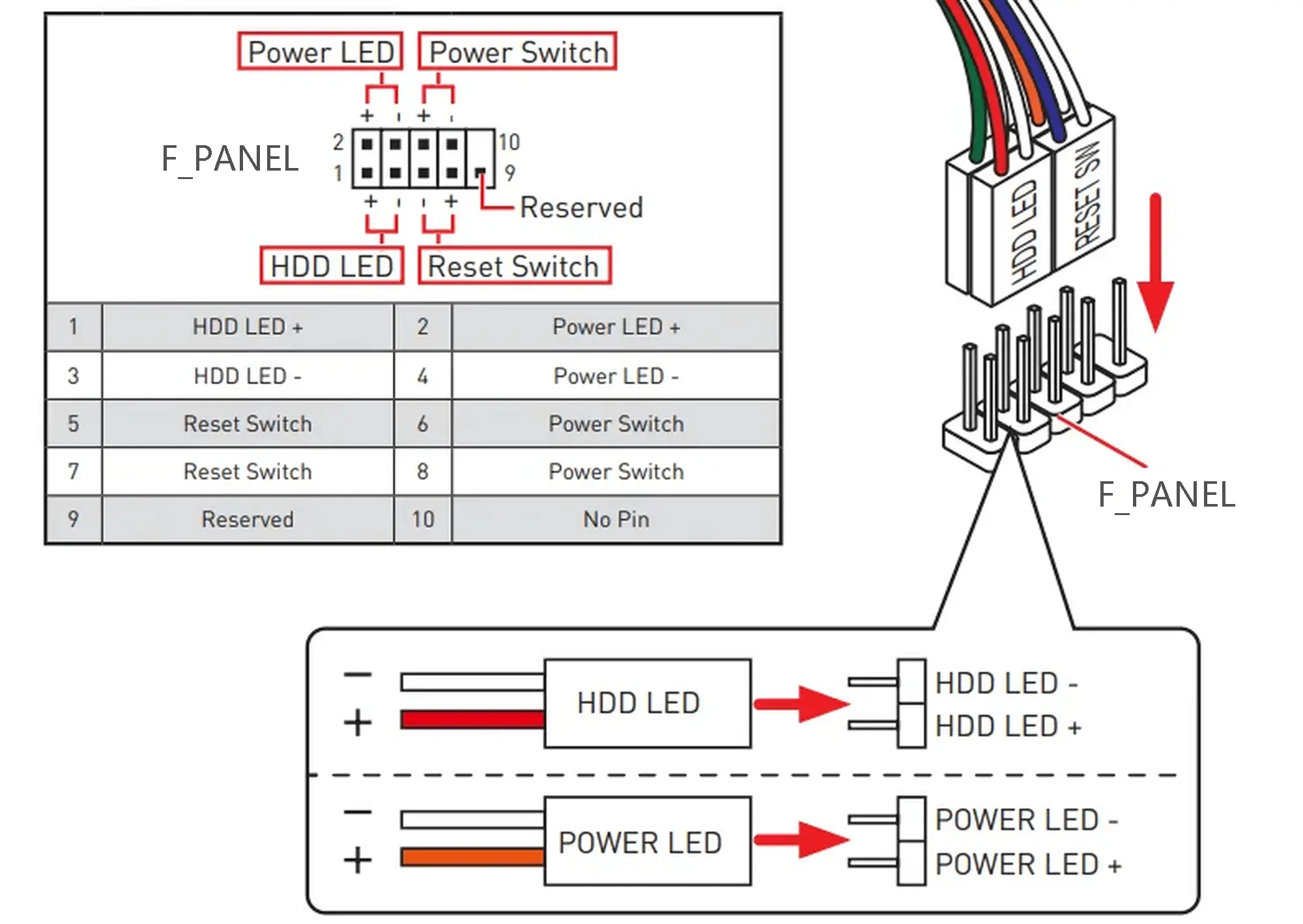
You can also use the F_PANEL interface to expand the power indicator light, which is a standard PC case front panel expansion interface.
Type-C
- The Type-C interface can be used as a burning port to install system-related images for the
SPI FLASH,eMMC module, andSSDon the board through a PC. - If you are running Bianbu Desktop in Jupiter, the Type-C interface is Adb Device by default, and you can connect to Jupiter via Adb on the PC.
- This Type-C interface supports PD power supply, which means you can power Jupiter through a PD power adapter.
eMMC Jumper
The eMMC jumper on the board does not need to be short-circuited when we use it. The system image can be burned into the eMMC normally and run. At this time, the boot program in the SPI Flash will be used to load the system in the eMMC.
If the eMMC jumper is shorted, the SPI Flash on the board will be disabled. In this scenario, you need to keep the eMMC jumper shorted when burning the system image and burn the bootloader into the eMMC as well.
F_PANEL Interface
F_PANEL is the abbreviation of Front Panel, which is a set of jumpers used to connect the front panel of a standard PC case. It includes four groups of signals: the power button, the reset button, the power indicator LED, and the HDD LED.
The Jupiter board will automatically power on after being powered by the method in the above Power Interfaces. There is no need to use the Power Button in F_PANEL. The function of the Power Button is to power off or power on again after powering off.

F_AUDIO、F_USB2、FUSB3 Interfaces
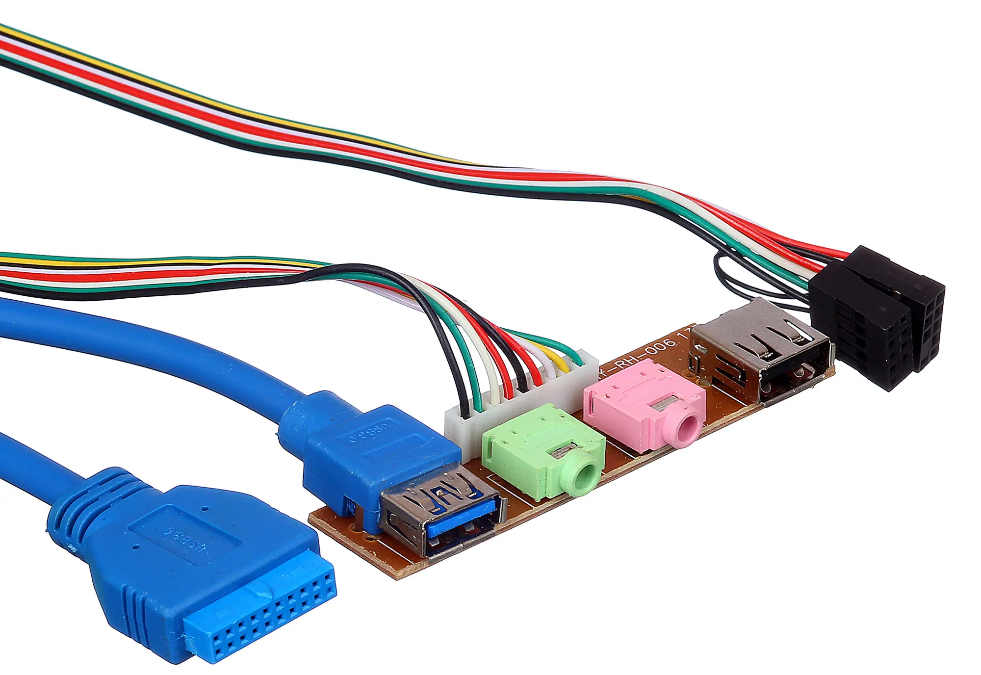
The following is a common standard PC case front panel USB and audio expansion interface board, including Audio, USB2.0 and USB3.0 interfaces. You can expand the USB and audio interfaces to the front panel of the PC case through the corresponding interfaces on the Jupiter board.
Jupiter board has built-in Audio, USB2.0, and USB3.0 interfaces, and the corresponding functions can be used normally without a PC case.
F_AUDIO
The F_AUDIO audio interface on the Jupiter board is compatible with the AC'97 front audio interface. The pin definitions are as follows:

| Description | PIN | PIN | Description |
|---|---|---|---|
| MIC_IN | 1 | 2 | GND |
| MIC_POWER | 3 | 4 | GND |
| AUDIO_OUT_R | 5 | 6 | RET_R(NC) |
| NC | 7 | ||
| AUDIO_OUT_L | 9 | 10 | RET_L(NC) |
F_USB2
The F_USB2 interface on the Jupiter board is compatible with the standard PC motherboard USB2.0 interface, and the pinout is defined as follows:
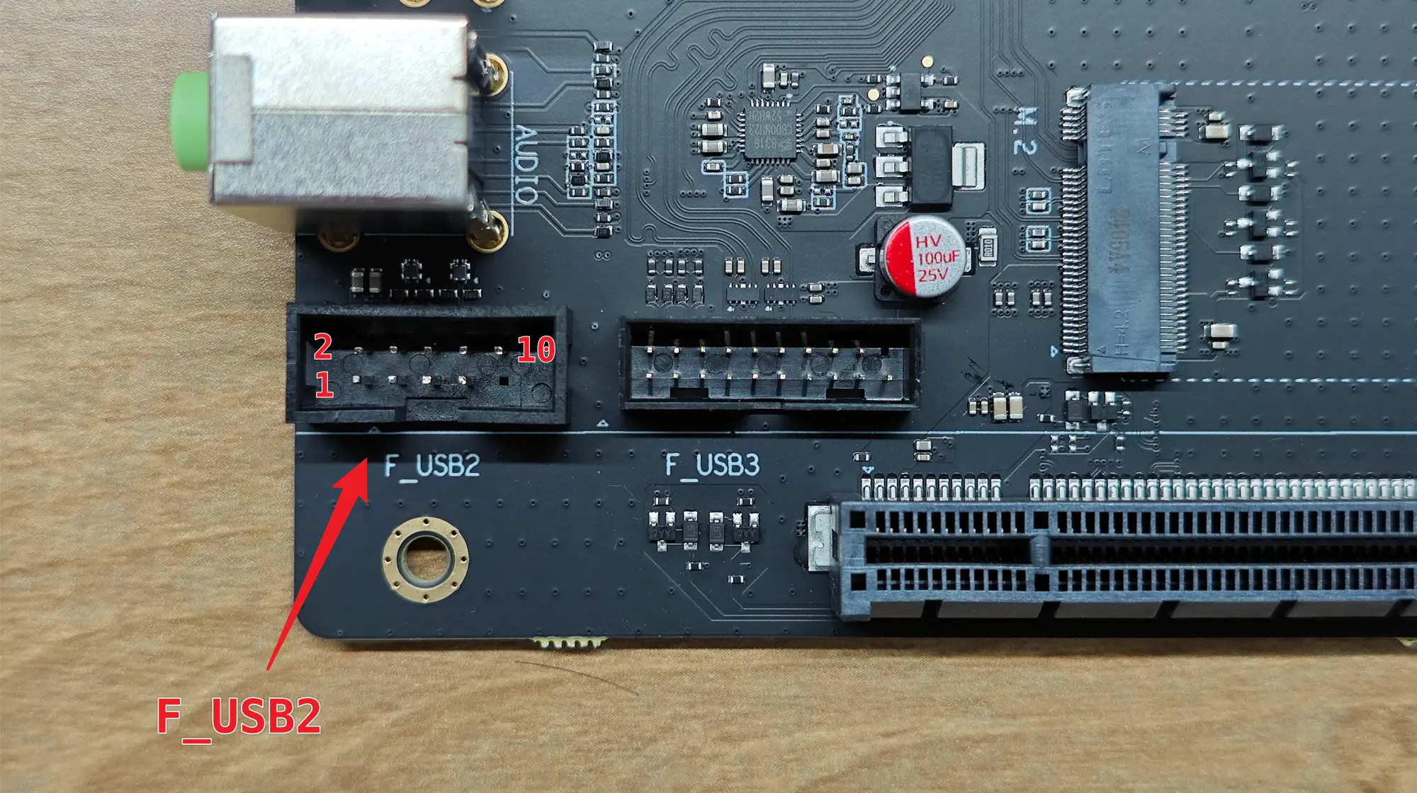
| Description | PIN | PIN | Description |
|---|---|---|---|
| 5V | 1 | 2 | 5V |
| USB1- | 3 | 4 | USB2- |
| USB1+ | 5 | 6 | USB2+ |
| GND | 7 | 8 | GND |
| 10 | GND |
F_USB3
The F_USB3 interface on the Jupiter board is compatible with the standard PC motherboard USB3.0 interface, and the pin definitions are as follows:
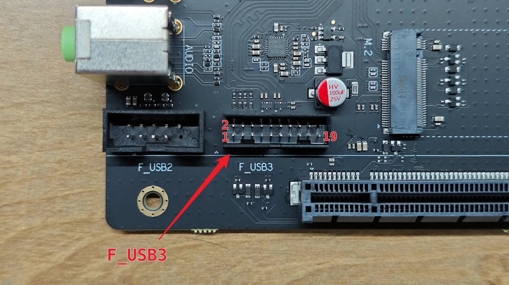
| Description | PIN | PIN | Description |
|---|---|---|---|
| ID | 1 | 2 | P2-D+ |
| P1-D+ | 3 | 4 | P2-D- |
| P1-D- | 5 | 6 | GND |
| GND | 7 | 8 | P2-SSTX+ |
| P1-SSTX+ | 9 | 10 | P2-SSTX- |
| P1-SSTX- | 11 | 12 | GND |
| GND | 13 | 14 | P2-SSRX+ |
| P1-SSRX+ | 15 | 16 | P2-SSRX- |
| P1-SSRX- | 17 | 18 | Vbus |
| Vbus | 19 |
SATA power connector
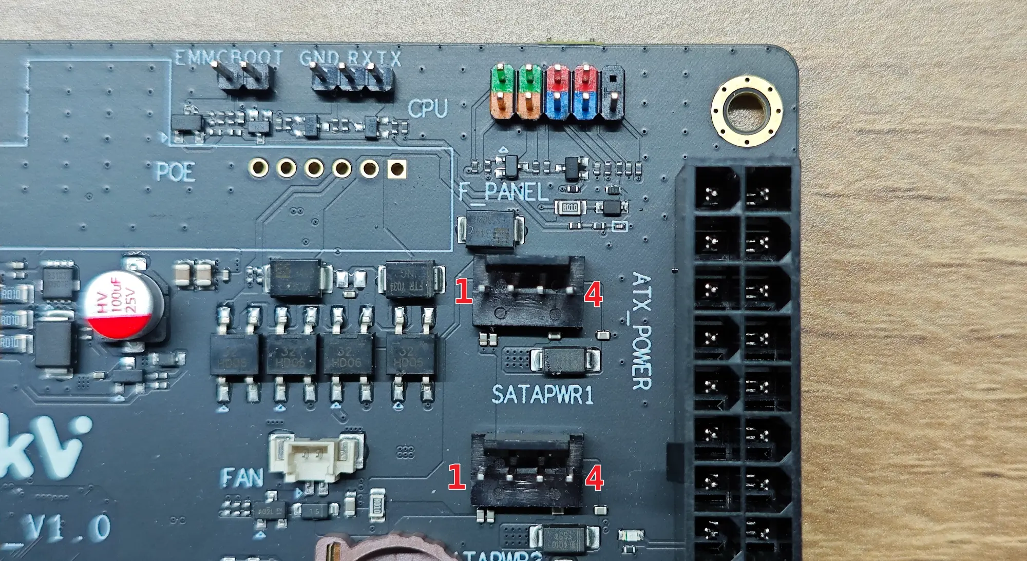
| PIN | Description |
|---|---|
| 1 | 5V |
| 2 | GND |
| 3 | GND |
| 4 | 12V |
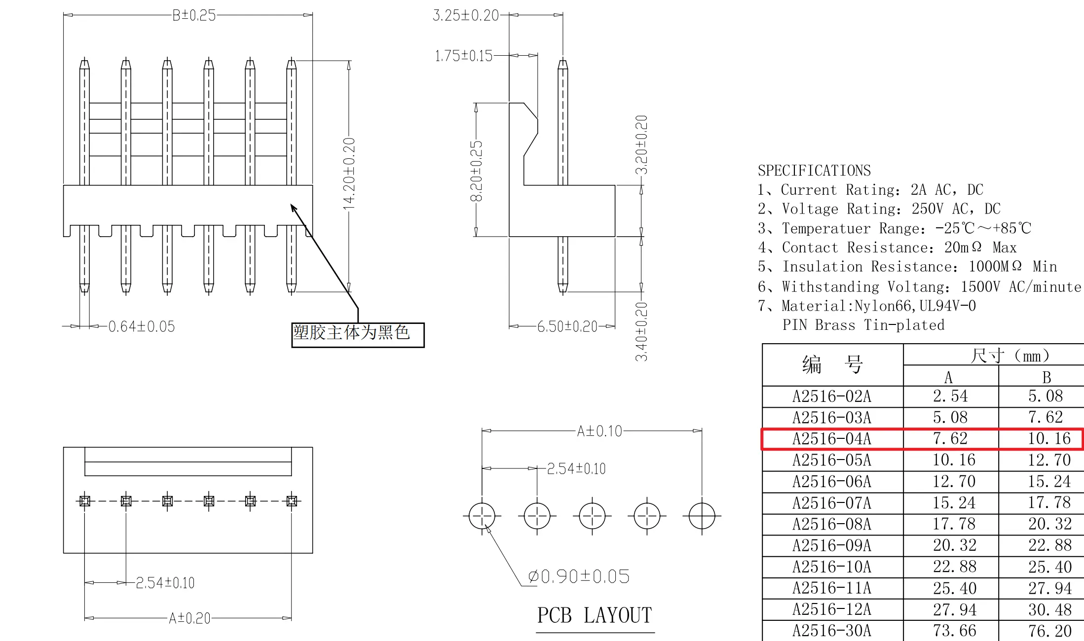
Connector Specifications:
