SPI Flash Firmware Update
Titan stores the UR-DP1000 boot firmware in SPI Flash. This guide explains how to remove the Flash chip, erase, program, and verify it with an external programmer, then reinstall it and check that the board boots. The hardware photos show Titan V2.1.
Flash Location and Specifications
The Flash chip is installed in an opening socket on the Titan motherboard and can be removed for offline programming. The socket is located as shown below:
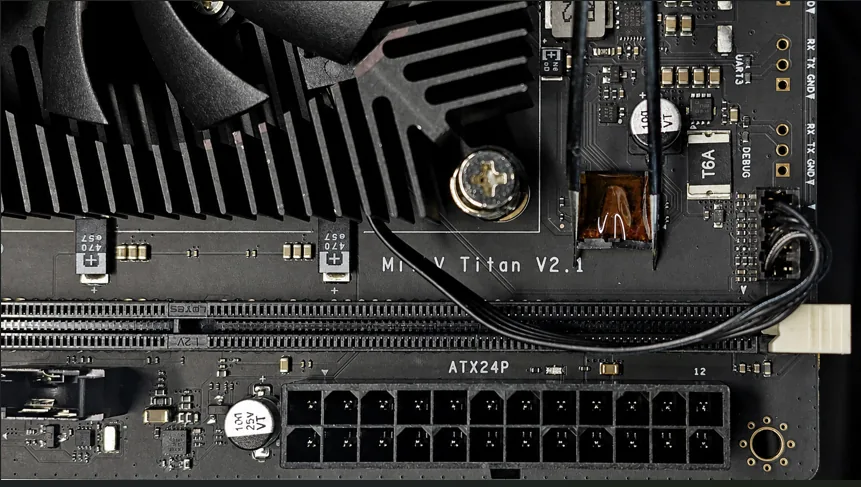
The red box in the following photo marks the Flash chip and its socket:
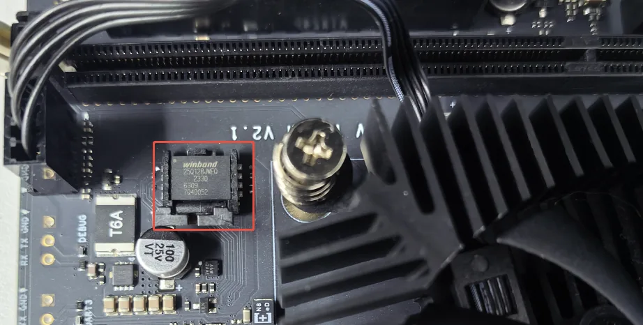
| Item | Specification |
|---|---|
| Chip model | Winbond W25Q128JWEQ |
| Capacity | 128 Mbit / 16 MB |
| I/O voltage | 1.8 V |
Prerequisites
The following programmer, socket adapter, and software are the reference combination used in this guide:
| Item | Description |
|---|---|
| Programmer | SFLY SP20B with a USB data cable |
| Socket adapter | SF-QFN8-8X6A |
| Programming software | SFLY FlyPRO II |
| Firmware file | A boot firmware .bin file compatible with Titan |
| Other tools | A computer running the programming software and tweezers to open the onboard socket |
Boot firmware download: Titan Firmware.
Check the firmware file's source, version, and size before proceeding. Boot firmware, SSD operating system images, and BMC firmware serve different purposes. Use the boot firmware file intended for this procedure.
Shut down Titan and disconnect all power connections before removing or reinstalling the Flash chip. The chip uses 1.8 V I/O. If you use another programmer, confirm chip support, voltage settings, and socket compatibility.
Erasing clears the existing Flash contents. Backing up the original firmware with the programmer's read function is recommended. Do not disconnect the programmer or remove the chip during programming.
Offline Programming Procedure
1. Remove the Flash Chip
Confirm that the board is disconnected from power and note the chip's original orientation. Use tweezers to gently squeeze the metal latches on both sides of the socket's opening end toward the center. Once the lid releases, lift out the Flash chip carefully.
2. Connect the Programmer and Insert the Chip
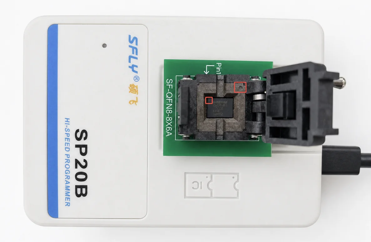
Install the SF-QFN8-8X6A socket adapter on the SFLY SP20B programmer, then connect the programmer to your computer with a USB data cable.
Open the adapter and insert the Flash chip in the orientation shown below. Use the dot on the chip as the Pin 1 marker and check it against the adapter's Pin 1 marking. Make sure the chip sits flat with its pads aligned to the contacts, then close and lock the socket.
3. Configure Programming Options
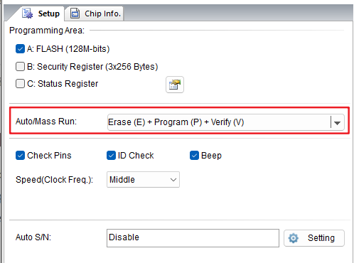
Start SFLY FlyPRO II and confirm that it recognizes the SP20B programmer. Under Operation Options, set the automatic/batch operation to Erase + Program + Verify:
4. Load the Firmware and Select the Chip
- Click Load File on the toolbar, select the prepared
.binfirmware file, and confirm that it is loaded correctly in the information area. - Open Chip → Identify Chip Model and select
Winbond W25Q128JWxxQ [WSON8(8x6)]from the detected models. - Check the chip information on the left. Confirm the model and capacity; the capacity should be
128M-bits / 16777216 Bytes.
The following screenshot marks the file loading, chip selection, and Auto controls:

5. Erase, Program, and Verify
Click Auto on the toolbar. The software performs the following operations in order:
- Pin contact check: Check contact between the chip and socket.
- Chip initialization: Check the chip model and placement.
- Erase: Clear the existing Flash contents.
- Program: Write the firmware file to Flash.
- Verify: Confirm that the written data matches the firmware file.
An error at any stage stops the operation. Check the software's information window for the error message. Remove the chip only after verification has passed.
| SP20B indicator | Status |
|---|---|
| Green | After programming completes, indicates success; the chip can be removed |
| Red | Programming failed; check the software's information window |
| Blue | Working or waiting for a chip to be inserted |
6. Reinstall the Chip and Check Boot
Open the programming socket and carefully remove the chip without damaging its pads or the socket contacts. With Titan still disconnected from power, reinstall the chip in its original orientation, confirm that it is seated correctly, and close the lid.
Reconnect power and start Titan. Confirm that the boot firmware runs normally. You can use the serial console to inspect the boot log and help check the update result.
Troubleshooting
| Symptom | Checks |
|---|---|
| Chip does not fit in the socket | Confirm that the adapter is SF-QFN8-8X6A and check chip orientation. Do not force the chip into place |
| Pin contact check fails | Check that the chip sits flat, its pads align with the contacts, and the socket is locked |
| Chip initialization fails | Check the selected chip model, socket adapter, and chip orientation |
| Programming or verification fails | Follow the error message in the software's information window. Complete verification successfully before reinstalling the chip |
| Programming succeeds but the board does not boot | Check chip orientation and contact, confirm that the firmware matches Titan, and check the programming address settings |