Introduction
Arduino is a popular open-source hardware platform known for its simplicity, ease of use, and openness. It provides a rich collection of library functions and example code, making it accessible even for individuals without programming experience. Additionally, the Arduino community is highly active, allowing easy access to a wide range of project tutorials, documentation, and support.
Milk-V Duo series now supports Arduino development. You can directly use the Arduino IDE and, after a simple configuration, start using it.
The Duo series CPU adopts a big-little core design, where the Arduino firmware runs on the little core, while the big core is responsible for communication with the Arduino IDE. It receives the Arduino firmware and loads it onto the little core for execution. At the same time, the Linux system in the big core also operates normally.
In addition, the Duo series board already supports the visual programming software VISUINO. For related content, please refer to this chapter: VISUINO.
1. Development Environment Setup
Install Arduino IDE
Arduino IDE supports three operating systems: Windows, Linux, and macOS. According to the system you are using, go to Arduino official website to download the corresponding installation package for installation. The current latest version is 2.3.2, and it is recommended to use the latest version.
Add Duo to Arduino IDE
Open Arduino IDE, select Preferences in the File menu, and add the Duo configuration file address in the Additional boards manager URLs in the Settings tab:
https://github.com/kubuds/sophgo-arduino/releases/download/v0.2.5/package_sg200x_index.json
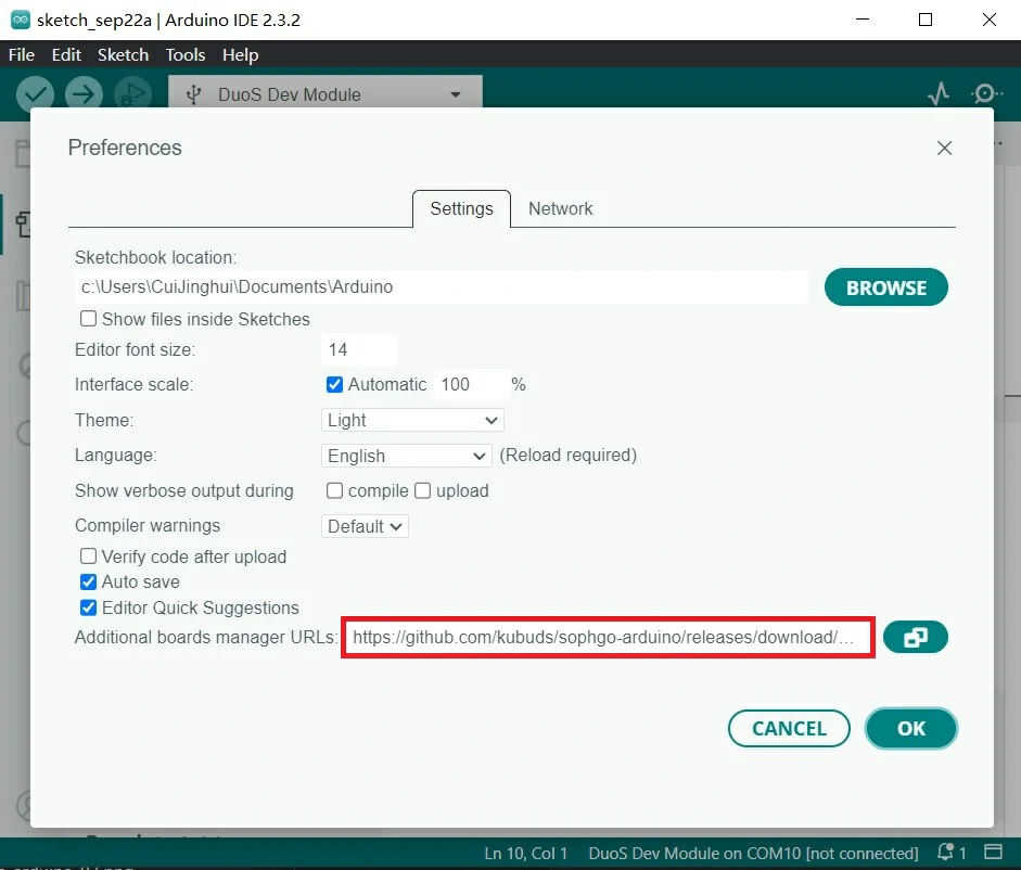
If you have configured other development board addresses before, separate them with commas, or click the icon on the right side of the address bar to bring up the window, and follow the prompts to add them.
After configuring, select Board in the Tools menu, open the Boards Manager, search for SG200X, and click Install.
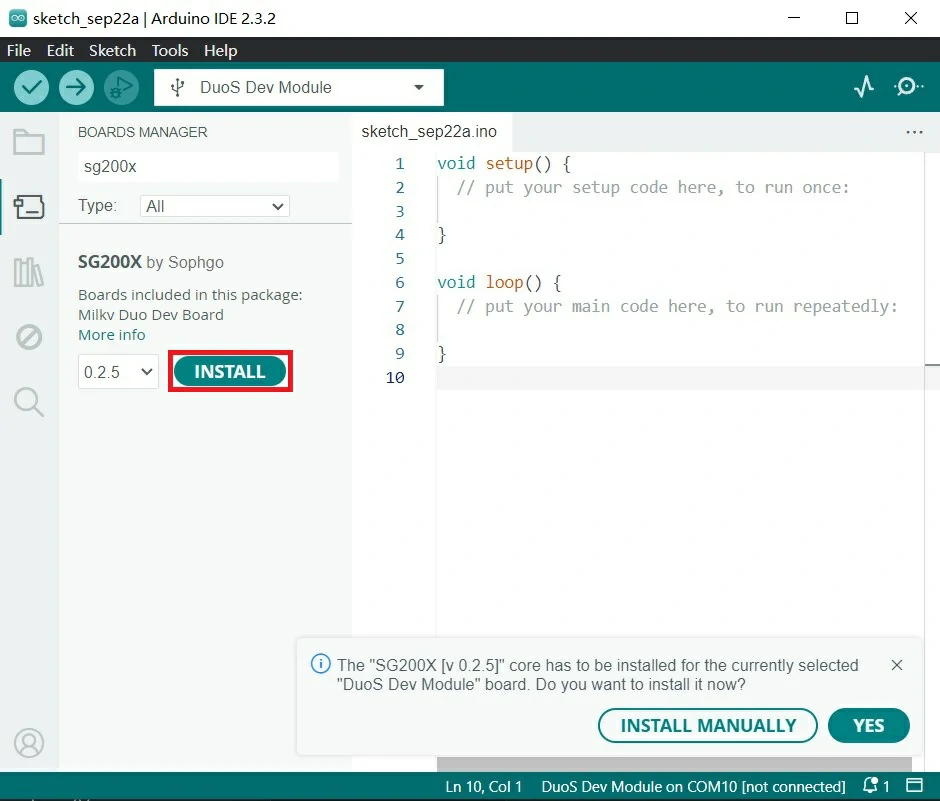
At this point, the Duo development environment in Arduino IDE has been installed. Now you can write and test the code.
Test blinking the onboard LED
Currently, Duo's SD card system needs to burn firmware that supports Arduino. Please download the firmware with the prefix arduino from Latest Release firmware.
The latest available Arduino firmware version is Duo-V1.1.2.
DuoS does not currently provide a ready-to-use Arduino version of the firmware. Please go to Buildroot SDK , clone it and switch to the arduino branch to compile.
Refer to Boot the Duo in the previous chapter to install the system.
Use a USB cable to connect Duo to your computer, and Duo will automatically power on.
Duo's default firmware, the large-core Linux system, will control the on-board LED flashing. This is achieved through the boot script. Now we are going to use the little-core Arduino to light up the LED. We need to disable the LED flashing script in the large-core Linux. In Duo's Execute in terminal:
mv /mnt/system/blink.sh /mnt/system/blink.sh_backup && sync
That is to say, rename the LED flashing script. After restarting Duo, the LED will no longer flash:
reboot
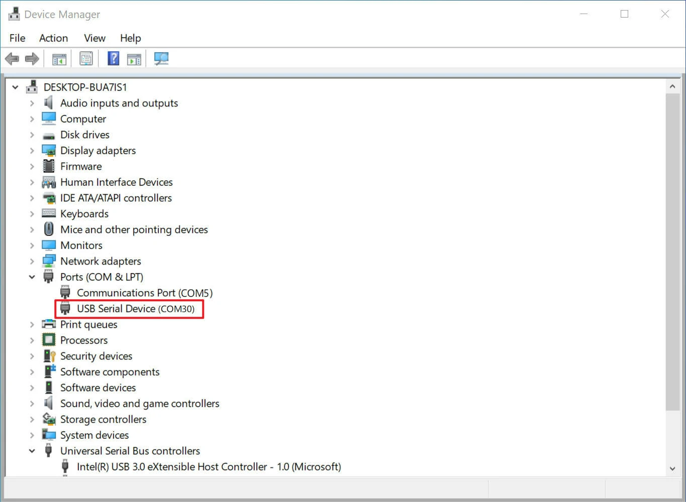
At this time, there will be an additional serial device in the "Port" of the "Device Manager" of the computer.
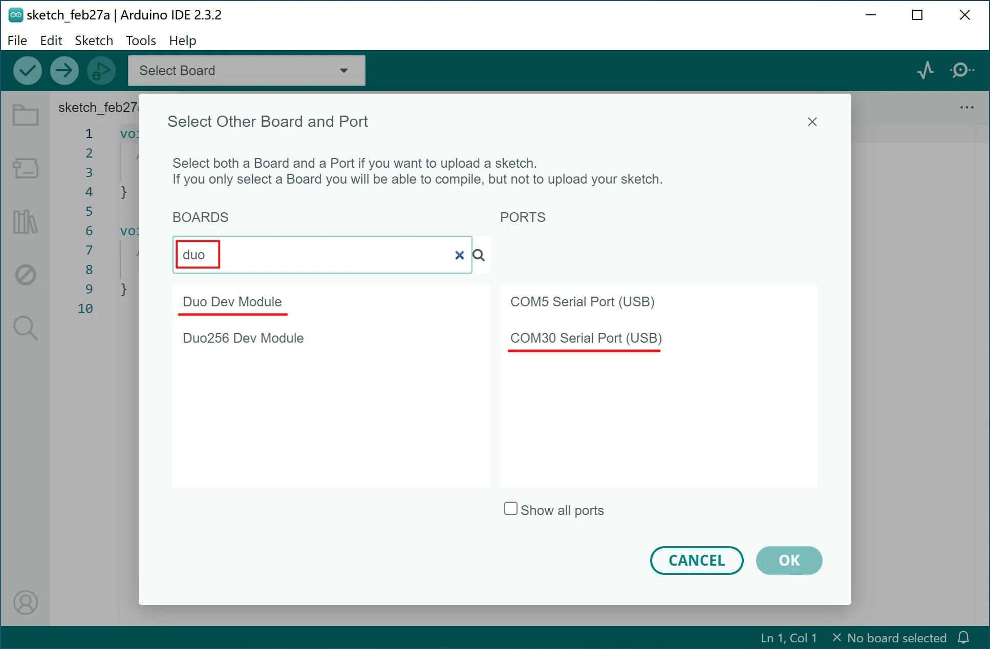
On the main interface of Arduino IDE, click Select Board, and then click Select other board and port...
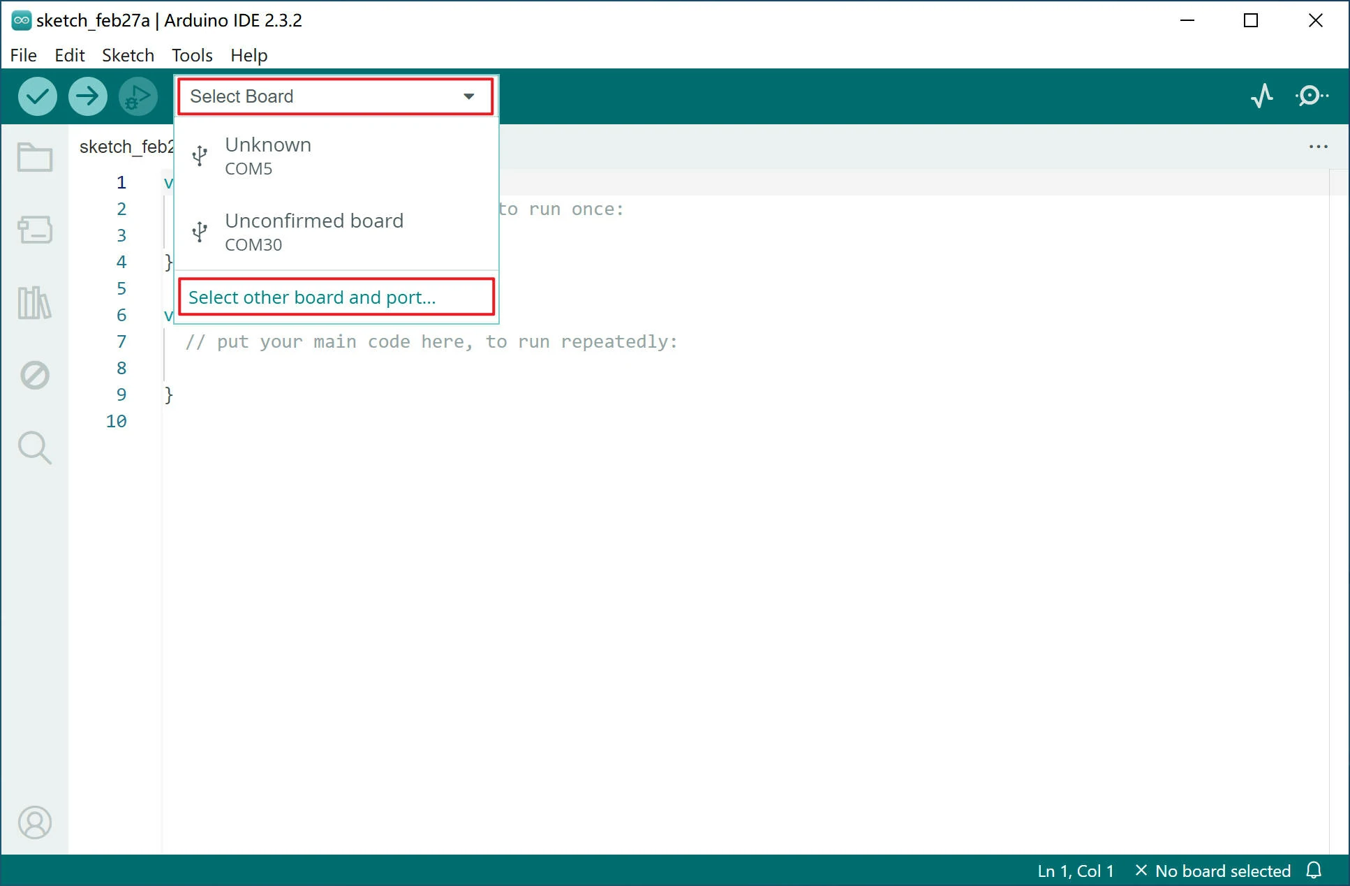
Search for "duo", select Duo Dev Module for Duo, select Duo256 Dev Module for Duo256M, select the corresponding serial port in the port and click OK.
Open the Examples > 01.Basics > Blink test program in the File menu of the Arduino IDE. The function of this program is to blink the onboard LED of the Arduino device. In Duo It is also supported. You may need to install pyserial in order to upload, and then let’s just click the Upload button to test:
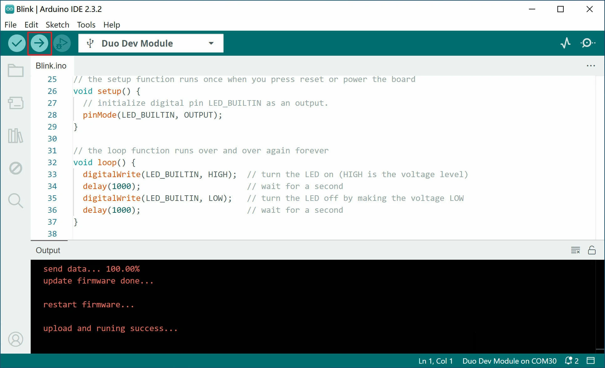
At this time, you can see the LED on the Duo board blinking at intervals of 1 second.
Before compiling and downloading the code, please make sure that you have installed the python environment on your computer and configured the environment variables correctly. The lack of the python environment may cause the code to fail to compile and download.
If you cannot download the firmware to the Duo, please check whether pyserial is installed first. If not, you can execute pip install pyserial to install it.
If you still cannot upload code to the Duo after installing pyserial, please check whether serial is installed on your computer. Installing both pyserial and serial at the same time may cause the firmware to fail to download. Please run pip uninstall serial to uninstall serial.
2. Duo Arduino pin resource
Duo
| SPI | PWM | I2C | UART | GPIO | NAME | PIN | PIN | NAME | GPIO | ADC |
|---|---|---|---|---|---|---|---|---|---|---|
| 1 | GP0 | 1 | 40 | VBUS | ||||||
| 2 | GP1 | 2 | 39 | VSYS | ||||||
| GND | 3 | 38 | GND | |||||||
| PWM7 | GP2 | 4 | 37 | 3V3_EN | ||||||
| PWM6 | GP3 | 5 | 36 | 3V3(OUT) | ||||||
| PWM5 | UART3_TX | GP4 | 6 | 35 | ||||||
| PWM6 | UART3_RX | GP5 | 7 | 34 | ||||||
| GND | 8 | 33 | GND | |||||||
| SPI2_SCK | PWM9 | I2C3_SDA | GP6 | 9 | 32 | GP27 | ||||
| SPI2_MOSI | PWM8 | I2C3_SCL | GP7 | 10 | 31 | GP26 | ADC1 | |||
| SPI2_MISO | PWM7 | I2C1_SDA | GP8 | 11 | 30 | RUN | ||||
| SPI2_CSn | PWM4 | I2C1_SCL | GP9 | 12 | 29 | GP22 | ||||
| GND | 13 | 28 | GND | |||||||
| PWM10 | I2C2_SDA | 14 | GP10 | 14 | 27 | GP21 | 27 | |||
| PWM11 | I2C2_SCL | 15 | GP11 | 15 | 26 | GP20 | 26 | |||
| PWM4 | GP12 | 16 | 25 | GP19 | 25 | |||||
| PWM5 | GP13 | 17 | 24 | GP18 | 24 | |||||
| GND | 18 | 23 | GND | |||||||
| 19 | GP14 | 19 | 22 | GP17 | 22 | |||||
| 20 | GP15 | 20 | 21 | GP16 | 21 | |||||
| 0 | LED |
Duo256M
| SPI | PWM | I2C | UART | GPIO | NAME | PIN | PIN | NAME | GPIO | ADC |
|---|---|---|---|---|---|---|---|---|---|---|
| 1 | GP0 | 1 | 40 | VBUS | ||||||
| 2 | GP1 | 2 | 39 | VSYS | ||||||
| GND | 3 | 38 | GND | |||||||
| PWM7 | GP2 | 4 | 37 | 3V3_EN | ||||||
| PWM6 | GP3 | 5 | 36 | 3V3(OUT) | ||||||
| PWM5 | UART3_TX | GP4 | 6 | 35 | ||||||
| PWM6 | UART3_RX | GP5 | 7 | 34 | ||||||
| GND | 8 | 33 | GND | |||||||
| SPI2_SCK | PWM9 | I2C3_SDA | GP6 | 9 | 32 | GP27 | ||||
| SPI2_MOSI | PWM8 | I2C3_SCL | GP7 | 10 | 31 | GP26 | ADC1 | |||
| SPI2_MISO | PWM7 | I2C1_SDA | GP8 | 11 | 30 | RUN | ||||
| SPI2_CSn | PWM4 | I2C1_SCL | GP9 | 12 | 29 | GP22 | ||||
| GND | 13 | 28 | GND | |||||||
| PWM10 | I2C2_SDA | 14 | GP10 | 14 | 27 | GP21 | 27 | |||
| PWM11 | I2C2_SCL | 15 | GP11 | 15 | 26 | GP20 | 26 | |||
| PWM4 | GP12 | 16 | 25 | GP19 | 25 | |||||
| PWM5 | GP13 | 17 | 24 | GP18 | 24 | |||||
| GND | 18 | 23 | GND | |||||||
| 19 | GP14 | 19 | 22 | GP17 | 22 | |||||
| 20 | GP15 | 20 | 21 | GP16 | 21 | |||||
| 0 | LED |
DuoS
GPIO on Header J3 (RJ45 Port side) use 3.3V logic levels.
| SPI | PWM | I2C | UART | NUM | SG2000 | NAME | PIN | PIN | NAME | SG2000 | NUM | UART | PWM | SPI | JTAG |
|---|---|---|---|---|---|---|---|---|---|---|---|---|---|---|---|
| 3V3 | 1 | 2 | VSYS(5V) | ||||||||||||
| PWM3 | I2C4_SCL | 468 | XGPIOB[20] | B20 | 3 | 4 | VSYS(5V) | ||||||||
| I2C4_SDA | 469 | XGPIOB[21] | B21 | 5 | 6 | GND | |||||||||
| I2C1_SCL | 466 | XGPIOB[18] | B18 | 7 | 8 | A16 | XGPIOA[16] | 496 | UART0_TX/UART1_TX | PWM4 | |||||
| GND* | 9 | 10 | A17 | XGPIOA[17] | 497 | UART0_RX/UART1_RX | PWM5 | ||||||||
| PWM1 | I2C1_SDA | UART2_TX | 459 | XGPIOB[11] | B11 | 11 | 12 | B19 | XGPIOB[19] | 467 | UART2_TX | PWM2 | |||
| PWM2 | I2C1_SCL | UART2_RX | 460 | XGPIOB[12] | B12 | 13 | 14 | GND | |||||||
| UART2_RX | 470 | XGPIOB[22] | B22 | 15 | 16 | A20 | XGPIOA[20] | 500 | JTAG_TRST | ||||||
| 3V3 | 17 | 18 | A19 | XGPIOA[19] | 499 | UART1_TX/UART1_RTS | PWM7 | JTAG_TMS | |||||||
| SPI3_SDO | PWM3 | I2C2_SCL | 461 | XGPIOB[13] | B13 | 19 | 20 | GND | |||||||
| SPI3_SDI | I2C2_SDA | 462 | XGPIOB[14] | B14 | 21 | 22 | A18 | XGPIOA[18] | 498 | UART1_RX/UART1_CTS | PWM6 | JTAG_TCK | |||
| SPI3_SCK | UART2_TX | 463 | XGPIOB[15] | B15 | 23 | 24 | B16 | XGPIOB[16] | 464 | UART2_RX | SPI3_CS | ||||
| GND | 25 | 26 | A28 | XGPIOA[28] | 508 | UART2_TX/UART1_TX |
GND*: Pin 9 is a low-level GPIO in the V1.1 version of the hardware, and is GND in the V1.2 version and later.
NOTE: The I2C on the CSI camera connector J2 is I2C2, so when using the CSI camera on J2, I2C2 in the J3 pin header is not available.
GPIO on Header J4(USB-A Port side) use 1.8V logic levels.
| PWM | I2C | UART | MIPI DSI | NUM | SG2000 | NAME | PIN | PIN | NAME | SG2000 | NUM | MIPI DSI |
|---|---|---|---|---|---|---|---|---|---|---|---|---|
| VSYS(5V) | 52 | 51 | AUDIO_OUT_R | |||||||||
| PWM12 | I2C4_SCL | UART3_TX | 449 | XGPIOB[1] | B1 | 50 | 49 | AUDIO_OUT_L | ||||
| PWM13 | I2C4_SDA | UART3_RX | 450 | XGPIOB[2] | B2 | 48 | 47 | AUDIO_IN_R | ||||
| 451 | XGPIOB[3] | B3 | 46 | 45 | AUDIO_IN_L | |||||||
| PWM10 | I2C2_SDA | LCD_RST | 354 | PWR_GPIO[2] | E2 | 44 | 43 | 3V3 | ||||
| PWM9 | I2C2_SCL | UART2_RX | LCD_PWR_CT | 353 | PWR_GPIO[1] | E1 | 42 | 41 | C18 | XGPIOC[18] | 434 | MIPI_TX_3N |
| PWM8 | UART2_TX | LCD_PWM | 352 | PWR_GPIO[0] | E0 | 40 | 39 | C19 | XGPIOC[19] | 435 | MIPI_TX_3P | |
| GND | 38 | 37 | GND | |||||||||
| MIPI_TX_2N | 436 | XGPIOC[20] | C20 | 36 | 35 | C16 | XGPIOC[16] | 432 | MIPI_TX_CN | |||
| MIPI_TX_2P | 437 | XGPIOC[21] | C21 | 34 | 33 | C17 | XGPIOC[17] | 433 | MIPI_TX_CP | |||
| GND | 32 | 31 | GND | |||||||||
| MIPI_TX_1N | 430 | XGPIOC[14] | C14 | 30 | 29 | C12 | XGPIOC[12] | 428 | MIPI_TX_0N | |||
| MIPI_TX_1P | 431 | XGPIOC[15] | C15 | 28 | 27 | C13 | XGPIOC[13] | 429 | MIPI_TX_0P |
In DuoS, SPI, I2C1/2, and ADC are temporarily unavailable. Please wait for subsequent software updates.
3. Code example
GPIO Usage Example
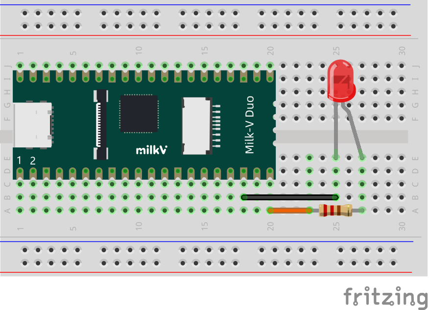
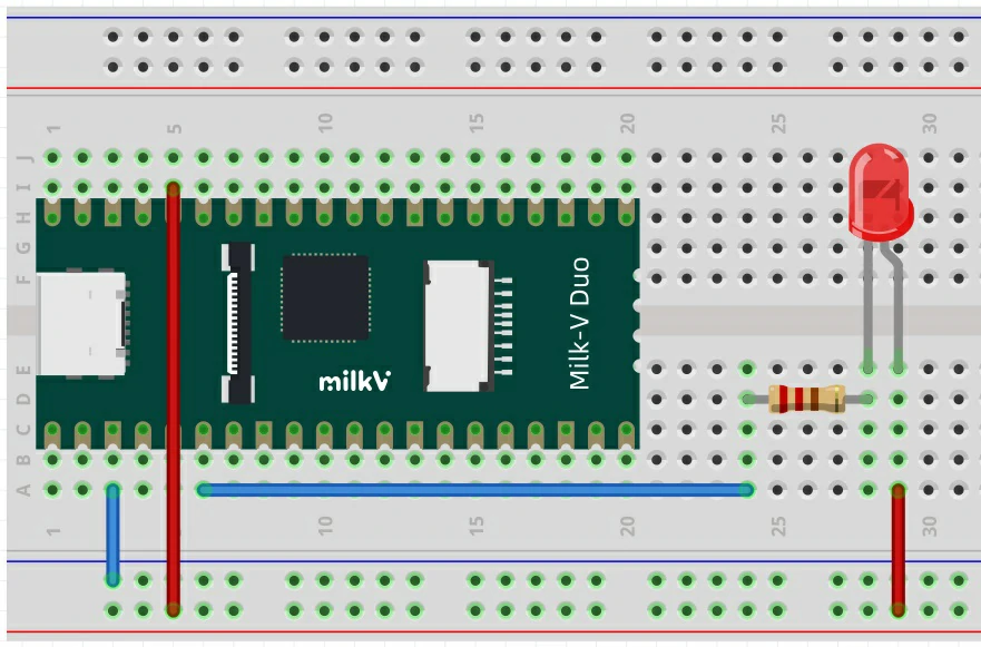
This program implements Duo physical pin 20 to output high and low levels cyclically with an interval of 1 second, and observe the phenomenon through an external LED.
The connection method is as follows. The negative pole of the LED is connected to the ground of the Duo (for example, pin 18), and the positive pole is connected in series with a 1K resistor and then connected to pin 20:
test code:
#define TEST_PIN 20  //0,1,2,14,15,19,20,21,22,24,25,26,27

// the setup function runs once when you press reset or power the board
void setup() {
  pinMode(TEST_PIN, OUTPUT);
}

// the loop function runs over and over again forever
void loop() {
  digitalWrite(TEST_PIN, HIGH); // turn the TEST_PIN on (HIGH is the voltage level)
  delay(1000);                  // wait for a second
  digitalWrite(TEST_PIN, LOW);  // turn the TEST_PIN off by making the voltage LOW
  delay(1000);                  // wait for a second
}
- If the LED is not connected, you can observe the status changes of the pin through a multimeter or oscilloscope.
- Configuring TEST_PIN to 0 enables testing of the Duo onboard LED.
UART Usage Example
UART Serial port
The UART serial port uses UART3 on physical pin 6/7 by default. When debugging the Arduino program, you can print debugging information through this serial port.
If you are using a DuoS board, UART3 is mapped to the 50/48 pins by default. Because the 50/48 pins use 1.8V level, it may be inconvenient to use. It is recommended that you use UART2 instead.
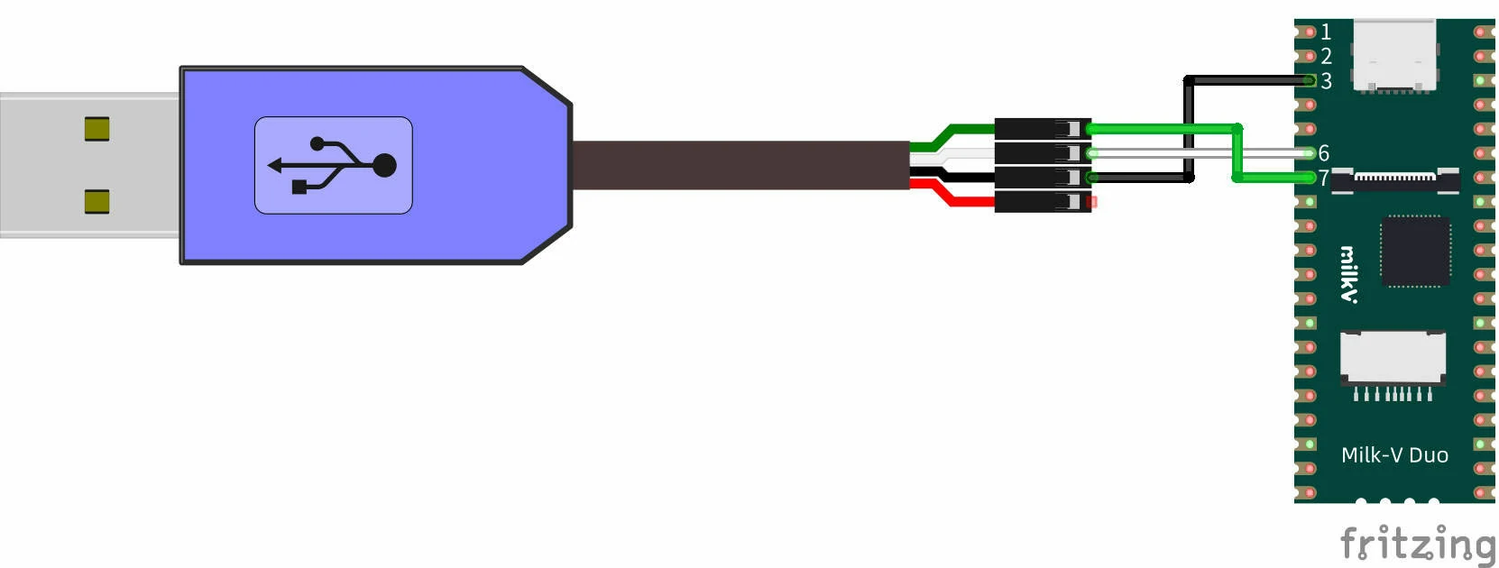
The connection method is as follows. The computer can use a USB to TTL serial port cable. The logic level is 3.3V and the baud rate is 115200. The RX of the serial port cable is connected to the PIN 6 UART3_TX of the Duo. The TX of the serial port cable is connected to the PIN 7 UART3_RX of the Duo. The serial port The GND of the line is connected to any GND of the Duo, such as pin 3:
test code:
void setup() {
  Serial.begin(115200);
}

void loop() {
  Serial.printf("hello world\r\n");
  delay(1000);
}
After running, you can see the "hello world" string printed every 1 second in the computer serial port tool:
hello world
hello world
In addition, the default serial port uses Duo's UART3 interface, so Serial3 can also be used in the program:
void setup() {
  Serial3.begin(115200);
}

void loop() {
  Serial3.printf("hello world\r\n");
  delay(1000);
}
I2C Usage Example
The I2C interface resources of Duo and Duo256M are different and need to be used according to the previous pin resource diagram.
I2C0 sends data to I2C1 (Duo)
The hardware connection is as follows. Connect the SDA and SCL pins of I2C0 and I2C1 correspondingly, and then connect the serial port to the computer to view the printing information according to the method in the UART example above.

The Wire function in Duo is mapped to I2C0 by default, that is, Wire is equivalent to Wire0.
Test code:
#include <Wire.h>

void receive(int a) {
  Serial.printf("receive %d bytes\n\r", a);
  while(a--) {
    Serial.printf("%d \n\r", Wire1.read());
  }
}

void setup() {
  Serial.begin(115200);
  Wire1.begin(0x50);
  Wire1.onReceive(receive);
  Wire.begin();
  Serial.printf("test slave\n\r");
  Wire1.print();
}

byte val = 0;

void loop() {
  Wire.beginTransmission(0x50);         // Transmit to device number 0x50
  Serial.printf("send %d \n\r", ++val);
  Wire.write(val);                      // Sends value byte
  Wire.endTransmission();               // Stop transmitting
  Wire1.onService();
  delay(1000);
}
Test Results:
test slave
Wire1: 1
[iic_dump_register]: ===dump start
IC_CON = 0x22
IC_TAR = 0x55
IC_SAR = 0x50
IC_SS_SCL_HCNT = 0x1ab
IC_SS_SCL_LCNT = 0x1f3
IC_ENABLE = 0x1
IC_STATUS = 0x6
IC_INTR_MASK = 0x224
IC_INTR_STAT = 0
IC_RAW_INTR_STAT = 0x10
[iic_dump_register]: ===dump end
send 1
receive 1 bytes
1
send 2
receive 1 bytes
2
send 3
receive 1 bytes
3
send 4
receive 1 bytes
4
I2C1 sends data to I2C2 (Duo256M)
Note that Duo256M does not have I2C0.
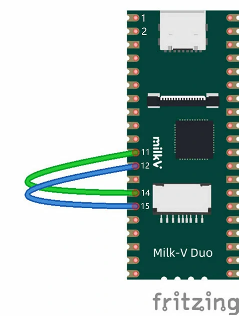
The hardware connection is as follows. Connect the SDA and SCL pins of I2C1 and I2C2 correspondingly, and then connect the serial port to the computer to view the printing information according to the method in the UART example above.
The Wire function in Duo256M is mapped to I2C1 by default, that is, Wire is equivalent to Wire1.
Test code:
#include <Wire.h>

void receive(int a) {
  Serial.printf("receive %d bytes\n\r", a);
  while(a--) {
    Serial.printf("%d \n\r", Wire2.read());
  }
}

void setup() {
  Serial.begin(115200);

  Wire2.begin(0x50);
  Wire2.onReceive(receive);

  Wire.begin();
  Serial.printf("test slave\n\r");
  Wire2.print();
}

byte val = 0;

void loop() {
  Wire.beginTransmission(0x50);         // Transmit to device number 0x50
  Serial.printf("send %d \n\r", ++val);
  Wire.write(val);                      // Sends value byte
  Wire.endTransmission();               // Stop transmitting
  Wire2.onService();
  delay(1000);
}
Test Results:
test slave
Wire2: 1
[iic_dump_register]: ===dump start
IC_CON = 0x22
IC_TAR = 0x55
IC_SAR = 0x50
IC_SS_SCL_HCNT = 0x1ab
IC_SS_SCL_LCNT = 0x1f3
IC_ENABLE = 0x1
IC_STATUS = 0x6
IC_INTR_MASK = 0x224
IC_INTR_STAT = 0
IC_RAW_INTR_STAT = 0x10
[iic_dump_register]: ===dump end
send 1
receive 1 bytes
1
send 2
receive 1 bytes
2
send 3
receive 1 bytes
3
send 4
receive 1 bytes
4
SPI Usage Example
SPI loopback test
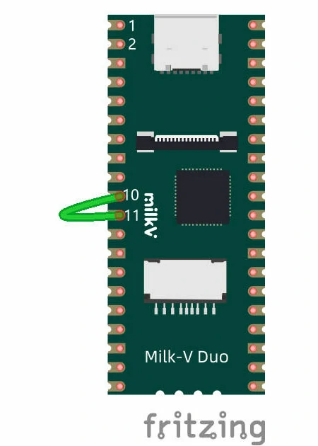
The hardware connection is as follows. Short-circuit the MOSI and MISO of the SPI, that is, pin 10 and pin 11, and then connect the serial port to the computer according to the method in the UART example above to view the printing information.
Test code:
#include <SPI.h>

char str[]="hello world\n";
void setup() {
  // put your setup code here, to run once:
  Serial.begin(115200);
  SPI.begin();
}

byte i = 0;

void loop() {
  // put your main code here, to run repeatedly:
  // digitalWrite(12, 1);
  SPI.beginTransaction(SPISettings());
  Serial.printf("transfer %c\n\r", str[i]);
  char out = SPI.transfer(str[i++]);        // spi loop back
  SPI.endTransaction();
  Serial.printf("receive %x \n\r", out);
  i %= 12;
}
Test Results:
receive a
transfer h
receive 68
transfer e
receive 65
transfer l
receive 6c
transfer l
receive 6c
transfer o
receive 6f
transfer
receive 20
transfer w
receive 77
transfer o
receive 6f
transfer r
receive 72
transfer l
receive 6c
transfer d
receive 64
transfer
PWM Usage Example
The hardware connection is as follows. Connect the DUO's GP4 to the negative lead of the LED.
Test code:
void setup() {
  pinMode(6, OUTPUT);
}

void loop() {
  for(int i = 128; i < 255; i++)
  {
    analogWrite(6,i);
    delay(50);
  }
  for(int i = 255; i > 128; i--)
  {
    analogWrite(6,i);
    delay(50);
  }
}
After compiling and burning, you can observe the LED light breathing effect.
Please pay attention to the allocation of PWM resources when using PWM. The same PWM can be assigned to two different pins, but the outputs of the two pins are exactly the same.
ADC Usage Example
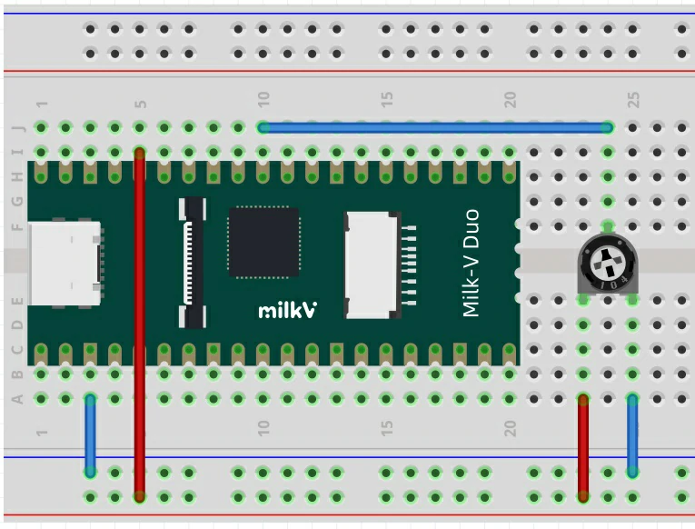
The hardware connection is as follows. Connect the GP26 of DUO to the signal pin of the potentiometer, and connect the other two pins to the positive and negative poles of the power supply respectively.
Test code:
int adc_get_val = 0;

void setup() {
  pinMode(0,OUTPUT);
}

void loop() {
  adc_get_val = analogRead(31);

  digitalWrite(0,HIGH);
  delay(adc_get_val);
  digitalWrite(0,LOW);
  delay(adc_get_val);
}
After compiling and burning, you can observe that the flashing frequency of the onboard LED changes as the position of the potentiometer changes.
MailBox Usage Example
Compile and burn the following code into the small core Arduino. This program can read the information sent by the large core from the MailBox and print it to the serial port, for serial port wiring, please refer to the UART Usage Example in this chapter.
#include "mailbox.h"

struct valid_t {
  uint8_t linux_valid;
  uint8_t rtos_valid;
} __attribute__((packed));

typedef union resv_t {
  struct valid_t valid;
  unsigned short mstime;  // 0 : noblock, -1 : block infinite
} resv_t;

typedef struct cmdqu_t cmdqu_t;
/* cmdqu size should be 8 bytes because of mailbox buffer size */
struct cmdqu_t {
  uint8_t ip_id;
  uint8_t cmd_id : 7;
  uint8_t block : 1;
  union resv_t resv;
  unsigned int param_ptr;
} __attribute__((packed)) __attribute__((aligned(0x8)));

void showmsg(MailboxMsg msg) {
  cmdqu_t *cmdq;
  Serial.print("Get Msg: ");
  Serial.println(*(msg.data), HEX);
  cmdq = (cmdqu_t *)msg.data;
  Serial.printf("cmdq->ip_id = %d\r\n", cmdq->ip_id);
  Serial.printf("cmdq->cmd_id = %x\r\n", cmdq->cmd_id);
  Serial.printf("cmdq->block = %d\r\n", cmdq->block);
  Serial.printf("cmdq->para_ptr = %x\r\n", cmdq->param_ptr);
  *(msg.data) = 0;
}

void setup() {
  Serial.begin(115200);
  mailbox_init(false);
  mailbox_register(0, showmsg);
  mailbox_enable_receive(0);
  Serial.println("Mailbox Start");
}

void loop() {

}
Compile the test program mailbox_test and run it on large-core Linux. The test program has been stored in the duo-examples warehouse. You can refer to README for compilation.
After running, the big core Linux output:
C906B: cmd.param_ptr = 0x2
C906B: cmd.param_ptr = 0x3
Small core serial port printing:
Mailbox Start
Get Msg: 19300
cmdq->ip_id = 0
cmdq->cmd_id = 13
cmdq->block = 1
cmdq->para_ptr = 2
Get Msg: 19300
cmdq->ip_id = 0
cmdq->cmd_id = 13
cmdq->block = 1
cmdq->para_ptr = 3
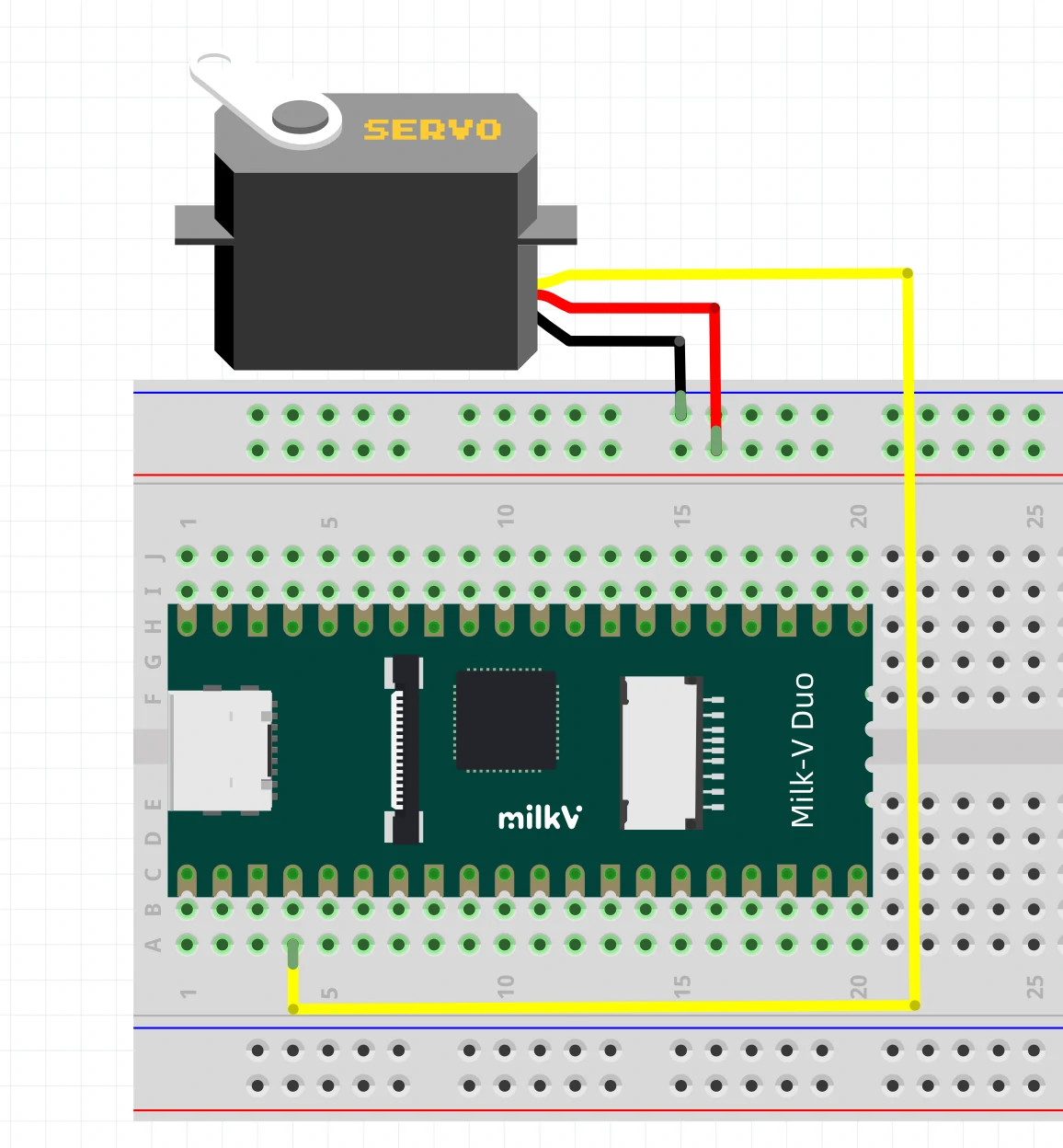
Servo Usage Example
First, please use our modified Servo library to replace the Servo library in the Arduino library directory. The default path of this library is C:\Users\[User name]\AppData\Local\Arduino15\libraries.
You can also find the following test code in the menu bar of Arduino-IDE, File - Examples - Servo - Sweep. Please note that you should change the pin number to the pin with PWM function.
Before burning the code, please check whether the servo is correctly connected to the pin.
#include <Servo.h>

Servo myservo;

int pos = 0;    // variable to store the servo position

void setup() {
  myservo.attach(4);  // attaches the servo on pin 4 to the Servo object
}

void loop() {
  for (pos = 0; pos <= 180; pos += 1) { // goes from 0 degrees to 180 degrees
    // in steps of 1 degree
    myservo.write(pos);              // tell servo to go to position in variable 'pos'
    delay(15);                       // waits 15 ms for the servo to reach the position
  }
  for (pos = 180; pos >= 0; pos -= 1) { // goes from 180 degrees to 0 degrees
    myservo.write(pos);              // tell servo to go to position in variable 'pos'
    delay(15);                       // waits 15 ms for the servo to reach the position
  }
}
After the program is burned, you can observe the connected servos swinging in cycles.
4. Sensor examples
L9110H_test
L9110H_test source:https://github.com/milkv-duo/duo-arduino-examples/tree/master/L9110H_test
For the example code of the DC motor driver chip L9110H, connect the wires according to the code comments and then burn and run. The motor will run in cycles of gradual acceleration and deceleration, and reverse gradual acceleration and deceleration.
LCD1602
LCD1602_test source:https://github.com/milkv-duo/duo-arduino-examples/tree/master/LCD1602_test
Example code for the LCD1602 I2C interface screen. Connect the wires according to the code comments and then burn and run. The screen will display a string.
LCD2004
LCD2004_test source:https://github.com/milkv-duo/duo-arduino-examples/tree/master/LCD2004_test
Example code for the LCD2004 I2C interface screen. Connect the wires according to the code comments and then burn and run. The screen will display a string.
Buzzer
buzzer_test source:https://github.com/milkv-duo/duo-arduino-examples/tree/master/buzzer_test
Example code for the buzzer module, wired according to the code comments and burned to run. The buzzer plays three different frequencies of beeps in a loop.
Buzzer Play Wave
buzzer_play_wave source:https://github.com/milkv-duo/duo-arduino-examples/tree/master/buzzer_play_wave
Example code for the buzzer module, wired according to the code comments and burned to run. The buzzer first plays seven notes in the key of C major, and then plays "Two Tigers" in a loop.
HC-SR04
hc_sr04_test source:https://github.com/milkv-duo/duo-arduino-examples/tree/master/hc_sr04_test
Example code for HC-SR04 ultrasonic distance measurement sensor module. After burning and running the example code, the board will print the measured distance data to the serial port.
RC522
rc522_test source:https://github.com/milkv-duo/duo-arduino-examples/tree/master/rc522_test
Example code for RC522 RFID read-write module. After burning and running the code, the board will loop to check if the ID card is read. If the ID card is detected, it will print the card type and card number information to the serial port.
SSD1306
ssd1306_test source:https://github.com/milkv-duo/duo-arduino-examples/tree/master/ssd1306_test
Example code for SSD1306 OLED screen module. After wiring according to comments and burning the code, the screen displays a dynamic animation of the eyes.
5. Arduino APIs
Digital I/O
digitalWrite()
void digitalWrite(uint8_t pinNumber, uint8_t status)
Write a HIGH or a LOW value to a digital pin.
digitalRead()
int digitalRead(uint8_t pinNumber)
Reads the value from a specified digital pin, either HIGH or LOW.
pinMode()
void pinMode(uint8_t pinNumber, uint8_t pinMode)
Configures the specified pin to behave either as an input or an output
Analog I/O
analogRead()
uint32_t analogRead(uint32_t pinNumber)
Reads the value from the specified analog pin.
analogReadResolution()
void analogReadResolution(int bits)
Sets the size (in bits) of the value returned by analogRead().
analogWrite()
void analogWrite(uint8_t pinNumber, uint32_t val)
Writes an analog value (PWM wave) to a pin.
analogWriteResolution()
void analogWriteResolution(int bits)
analogWriteResolution() sets the resolution of the analogWrite() function.
Wire(I2C)
begin()
void begin(csi_iic_addr_mode_t addr_mode = IIC_ADDRESS_7BIT);
void begin(uint16_t address, csi_iic_addr_mode_t addr_mode = IIC_ADDRESS_7BIT);
beginTransmission()
void beginTransmission(uint16_t);
endTransmission()
uint8_t endTransmission(bool stopBit);
uint8_t endTransmission(void);
requestFrom()
size_t requestFrom(uint16_t address, size_t quantity, bool stopBit);
size_t requestFrom(uint16_t address, size_t quantity);
write()
size_t write(uint8_t data);
size_t write(const uint8_t * data, size_t quantity);
available()
virtual int available(void);
read()
virtual int read(void);
onReceive()
void onReceive(void(*)(int));
onRequest()
void onRequest(void(*)(void));
Other functional interfaces and their usage in Duo will be updated in the future. You can also refer to Arduino official documentation first.