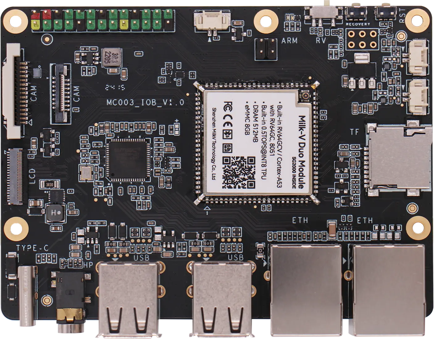
Duo Module 01

The Duo Module 01 is a compact module with integrated SG2000, WI-FI6/BTDM5.4, and eMMC. It supports SMD mounting. Also it can greatly save product development time. It is the first choice for making products.
In order to enable you to quickly verify and debug the initial product solution when designing products using Duo Module 01, We also provides an evaluation board (EVB), which is specially designed for the core board and provides rich interfaces and functions.
Introduction of SG2000
SG2000 is a high-performance, low-power chip designed for various product fields such as edge intelligent surveillance IP cameras, local facial recognition attendance machines, and smart home devices. It integrates H.264/H.265 video compression and decoding and ISP capabilities. It supports various image enhancement and correction algorithms like HDR wide dynamic range, 3D noise reduction, defogging, and lens distortion correction, providing customers with professional-grade video image quality.
The chip also integrates an in-house TPU, delivering approximately 0.5TOPS of computing power under INT8 operations. The specially designed TPU scheduling engine efficiently provides high-bandwidth data flow for tensor processing unit cores. It also offers users a powerful deep learning model compiler and software SDK development kit. Mainstream deep learning frameworks such as Caffe, Pytorch, ONNX, MXNet, and TensorFlow (Lite) can be easily ported to this platform.
SG2000 Public Preliminary Datasheet
We have open sourced the Public Preliminary Datasheet and TRM of SG2000 to GitHub. please check it out.
Purchase
Milk-V is the Authorised Global Distributor of the SG2000 chips. You can buy Duo Module 01 and samples of the SG2000 chip from our distributor online store directly. For volume order, please contact Milk-V Sales Team for the qoutation.
Getting Started
Installing the system
The software of Duo Module 01 is compatible with DuoS. Please use the firmware of DuoS directly.
-
Boot from SD card
Please refer to the Start Up section.
-
Boot from eMMC
Please refer to: eMMC version firmware burning section.
USB Network Usage
Please refer to the Setup section.
Duo Module 01 GPIO Pinout
GPIO pin mapping
| GROUP | ADDR | PORT | CHIP | NUM | NAME | START |
|---|---|---|---|---|---|---|
| gpio0 | gpio@03020000 | porta | gpiochip0 | 480-511 | XGPIOA | 480 - XGPIOA[0] |
| gpio1 | gpio@03021000 | portb | gpiochip1 | 448-479 | XGPIOB | 448 - XGPIOB[0] |
| gpio2 | gpio@03022000 | portc | gpiochip2 | 416-447 | XGPIOC | 416 - XGPIOC[0] |
| gpio3 | gpio@03023000 | portd | gpiochip3 | 384-415 | ||
| gpio4 | gpio@05021000 | porte | gpiochip4 | 352-383 | PWR_GPIO | 352 - PWR_GPIO[0] |
Pin Definition
| PIN | NAME | SG2000 | NUM | MIPI DSI |
|---|---|---|---|---|
1 | MIPI_TX_2N | XGPIOC[16] | 432 | MIPI_TX_CN |
2 | MIPI_TX_2P | XGPIOC[17] | 433 | MIPI_TX_CP |
3 | MIPI_TX_1N | XGPIOC[14] | 430 | MIPI_TX_1N |
4 | MIPI_TX_1P | XGPIOC[15] | 431 | MIPI_TX_1P |
5 | MIPI_TX_0N | XGPIOC[12] | 428 | MIPI_TX_0N |
6 | MIPI_TX_0P | XGPIOC[13] | 429 | MIPI_TX_0P |
7 | 3V3 | |||
8 | 3V3 | |||
9 | GND | |||
10 | SENSOR_HS0 | XGPIOA[1] | ||
11 | SENSOR_CLK1 | XGPIOA[3] | ||
12 | SENSOR_CLK0 | XGPIOA[0] | ||
13 | I2C3_SENSOR0_SDA | XGPIOA[6] | ||
14 | I2C3_SENSOR0_SCL | XGPIOA[5] | ||
15 | SENSOR_RSTN1 | XGPIOA[4] | ||
16 | SENSOR_RSTN0 | XGPIOA[2] | ||
17 | AUDIO_OUT_L | |||
18 | AUDIO_OUT_R | |||
19 | AUDIO_IN_L | |||
20 | AUDIO_IN_R | |||
21 | SD_SD0_D1 | XGPIOA[10] | ||
22 | SD_SD0_CMD | XGPIOA[8] |
| PIN | NAME | SG2000 | NUM | UART | PWM | JTAG | MIPI DSI | I2C |
|---|---|---|---|---|---|---|---|---|
23 | SD_SD0_CD | XGPIOA[13] | ||||||
24 | SD_SD0_D0 | XGPIOA[9] | ||||||
25 | SD_SD0_CLK | XGPIOA[7] | ||||||
26 | SD_SD0_D2 | XGPIOA[11] | ||||||
27 | SD_SD0_D3 | XGPIOA[12] | ||||||
28 | XGPIOB_22 | XGPIOB[22] | 470 | UART2_RX | ||||
29 | SD_PWR_EN | |||||||
30 | UART0_RX | PWR_GPIO[0] | 352 | UART2_TX | PWM8 | LCD_PWM | ||
31 | UART0_TX | XGPIOA[16] | 496 | UART0_TX/UART1_TX | PWM4 | |||
32 | XGPIOA_18 | XGPIOA[18] | 498 | UART1_RX/UART1_CTS | PWM6 | JTAG_TCK | ||
33 | XGPIOA_19 | XGPIOA[19] | 499 | UART1_TX/UART1_RTS | PWM7 | JTAG_TMS | ||
34 | XGPIOA_30 | XGPIOA[30] | ||||||
35 | PWR_VBAT_DET | |||||||
36 | LCD_RST | PWR_GPIO[2] | 354 | PWM10 | LCD_RST | I2C2_SDA | ||
37 | LCD_PWR_CT | |||||||
38 | LCD_PWM | |||||||
39 | I2C_SENSOR1_SDA | PWR_GPIO[13] | ||||||
40 | I2C_SENSOR1_SCL | PWR_GPIO[12] | ||||||
41 | XGPIOA_20 | XGPIOA[20] | 500 | JTAG_TRST | ||||
42 | XGPIOA_29 | XGPIOA[29] | ||||||
43 | XGPIOA_28 | XGPIOA[28] | 508 | UART2_TX/UART1_TX | ||||
44 | VDD_BAT |
| PIN | NAME | SG2000 | NUM | UART | PWM | SPI | I2C |
|---|---|---|---|---|---|---|---|
45 | PWM0_BUCK | XGPIOB[0] | |||||
46 | VBUS_EN | XGPIOB[5] | |||||
47 | UPDATE | XGPIOB[4] | |||||
48 | VBUS_DET | XGPIOB[6] | |||||
49 | EPHY_LNK_LED | PWR_GPIO[6] | |||||
50 | EPHY_SPD_LED | PWR_GPIO[8] | |||||
51 | XGPIOB_12 | XGPIOB[12] | 460 | UART2_RX | PWM2 | I2C1_SCL | |
52 | XGPIOB_11 | XGPIOB[11] | 459 | UART2_TX | PWM1 | I2C1_SDA | |
53 | XGPIOB_13/SPI3_SDO | XGPIOB[13] | 461 | PWM3 | SPI3_SDO | I2C2_SCL | |
54 | XGPIOB_15/SPI3_SCK | XGPIOB[15] | 463 | UART2_TX | SPI3_SCK | ||
55 | XGPIOB_14/SPI3_SDI | XGPIOB[14] | 462 | SPI3_SDI | I2C2_SDA | ||
56 | XGPIOB_16/SPI3_CS | XGPIOB[16] | 464 | UART2_RX | SPI3_CS | ||
57 | ADC1 | XGPIOB[3] | 451 | ||||
58 | ADC2 | XGPIOB[2] | 450 | UART3_RX | PWM13 | I2C4_SDA | |
59 | ADC3 | XGPIOB[1] | 449 | UART3_TX | PWM12 | I2C4_SCL | |
60 | ARM_RISV_SWITCH | XGPIOB[23] | |||||
61 | EPHY_RXP | XGPIOB[24] | |||||
62 | EPHY_RXN | XGPIOB[25] | |||||
63 | EPHY_TXP | XGPIOB[26] | |||||
64 | EPHY_TXN | XGPIOB[27] | |||||
65 | USB_DM | ||||||
66 | USB_DP |
| PIN | NAME | SG2000 | NUM | UART | PWM | MIPI DSI | I2C |
|---|---|---|---|---|---|---|---|
67 | XGPIOB_17/I2C1_SDA | XGPIOB[17] | |||||
68 | XGPIOB_18/I2C1_SCL | XGPIOB[18] | 466 | I2C1_SCL | |||
69 | XGPIOB_19 | XGPIOB[19] | 467 | UART2_TX | PWM2 | ||
70 | XGPIOB_20/I2C4_SCL | XGPIOB[20] | 468 | UART2_TX | PWM3 | I2C4_SCL | |
71 | XGPIOB_21/I2C4_SDA | XGPIOB[21] | 469 | I2C4_SDA | |||
72 | MIPI0_DN5 | XGPIOC[0] | I2C4_SDA | ||||
73 | MIPI0_DP5 | XGPIOC[1] | |||||
74 | MIPI0_DN4 | XGPIOC[2] | |||||
75 | MIPI0_DP4 | XGPIOC[3] | |||||
76 | MIPI0_DN3 | XGPIOC[4] | |||||
77 | MIPI0_DP3 | XGPIOC[5] | |||||
78 | MIPI0_DN0 | XGPIOC[10] | |||||
79 | MIPI0_DP0 | XGPIOC[11] | |||||
80 | MIPI0_DN1 | XGPIOC[8] | |||||
81 | MIPI0_DP1 | XGPIOC[9] | |||||
82 | MIPI0_DN2 | XGPIOC[6] | |||||
83 | MIPI0_DP2 | XGPIOC[7] | |||||
84 | GND | ||||||
85 | MIPI_TX_4N | XGPIOC[18] | 434 | MIPI_TX_3N | |||
86 | MIPI_TX_4P | XGPIOC[19] | 435 | MIPI_TX_3P | |||
87 | MIPI_TX_3N | XGPIOC[20] | 436 | MIPI_TX_2N | |||
88 | MIPI_TX_3P | XGPIOC[21] | 437 | MIPI_TX_2P |
DuoModule 01 EVB GPIO Pinout
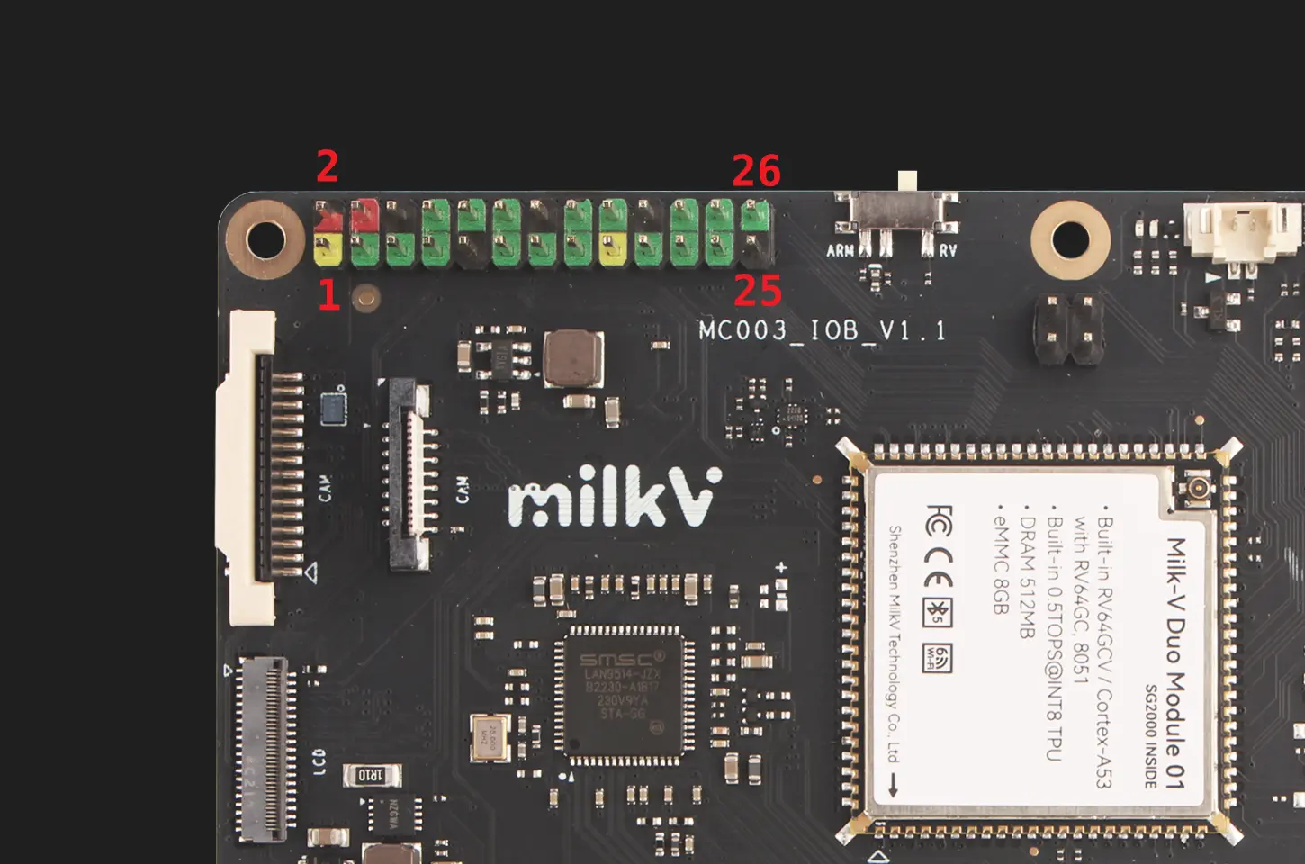
26 PIN Header
GPIO on 26 PIN Header use 3.3V logic levels.
| SPI | PWM | I2C | UART | NUM | SG2000 | NAME | PIN | PIN | NAME | SG2000 | NUM | UART | PWM | SPI | JTAG |
|---|---|---|---|---|---|---|---|---|---|---|---|---|---|---|---|
| 3V3 | 1 | 2 | VSYS(5V) | ||||||||||||
| PWM3 | I2C4_SCL | 468 | XGPIOB[20] | B20 | 3 | 4 | VSYS(5V) | ||||||||
| I2C4_SDA | 469 | XGPIOB[21] | B21 | 5 | 6 | GND | |||||||||
| I2C1_SCL | 466 | XGPIOB[18] | B18 | 7 | 8 | A16 | XGPIOA[16] | 496 | UART0_TX/UART1_TX | PWM4 | |||||
| GND | 9 | 10 | A17 | XGPIOA[17] | 497 | UART0_RX/UART1_RX | PWM5 | ||||||||
| PWM1 | I2C1_SDA | UART2_TX | 459 | XGPIOB[11] | B11 | 11 | 12 | B19 | XGPIOB[19] | 467 | UART2_TX | PWM2 | |||
| PWM2 | I2C1_SCL | UART2_RX | 460 | XGPIOB[12] | B12 | 13 | 14 | GND | |||||||
| UART2_RX | 470 | XGPIOB[22] | B22 | 15 | 16 | A20 | XGPIOA[20] | 500 | JTAG_TRST | ||||||
| 3V3 | 17 | 18 | A19 | XGPIOA[19] | 499 | UART1_TX/UART1_RTS | PWM7 | JTAG_TMS | |||||||
| SPI3_SDO | PWM3 | I2C2_SCL | 461 | XGPIOB[13] | B13 | 19 | 20 | GND | |||||||
| SPI3_SDI | I2C2_SDA | 462 | XGPIOB[14] | B14 | 21 | 22 | A18 | XGPIOA[18] | 498 | UART1_RX/UART1_CTS | PWM6 | JTAG_TCK | |||
| SPI3_SCK | UART2_TX | 463 | XGPIOB[15] | B15 | 23 | 24 | B16 | XGPIOB[16] | 464 | UART2_RX | SPI3_CS | ||||
| GND | 25 | 26 | A28 | XGPIOA[28] | 508 | UART2_TX/UART1_TX |
Blue LED PIN
| NAME | SG2000 | NUM |
|---|---|---|
LED | XGPIOA[29] | 509 |
Camera interface
Duo Module 01 EVB has two CSI camera connectors:
- J8 is a 16 PIN 0.5mm pitch connector compatible with Duo and Duo256M cameras, and can directly use the CAM-GC2083 camera.
- J10 is a 15-pin 1.0mm pitch connector compatible with the Raspberry Pi camera interface. It currently supports the OV5647 camera used on the Raspberry Pi.
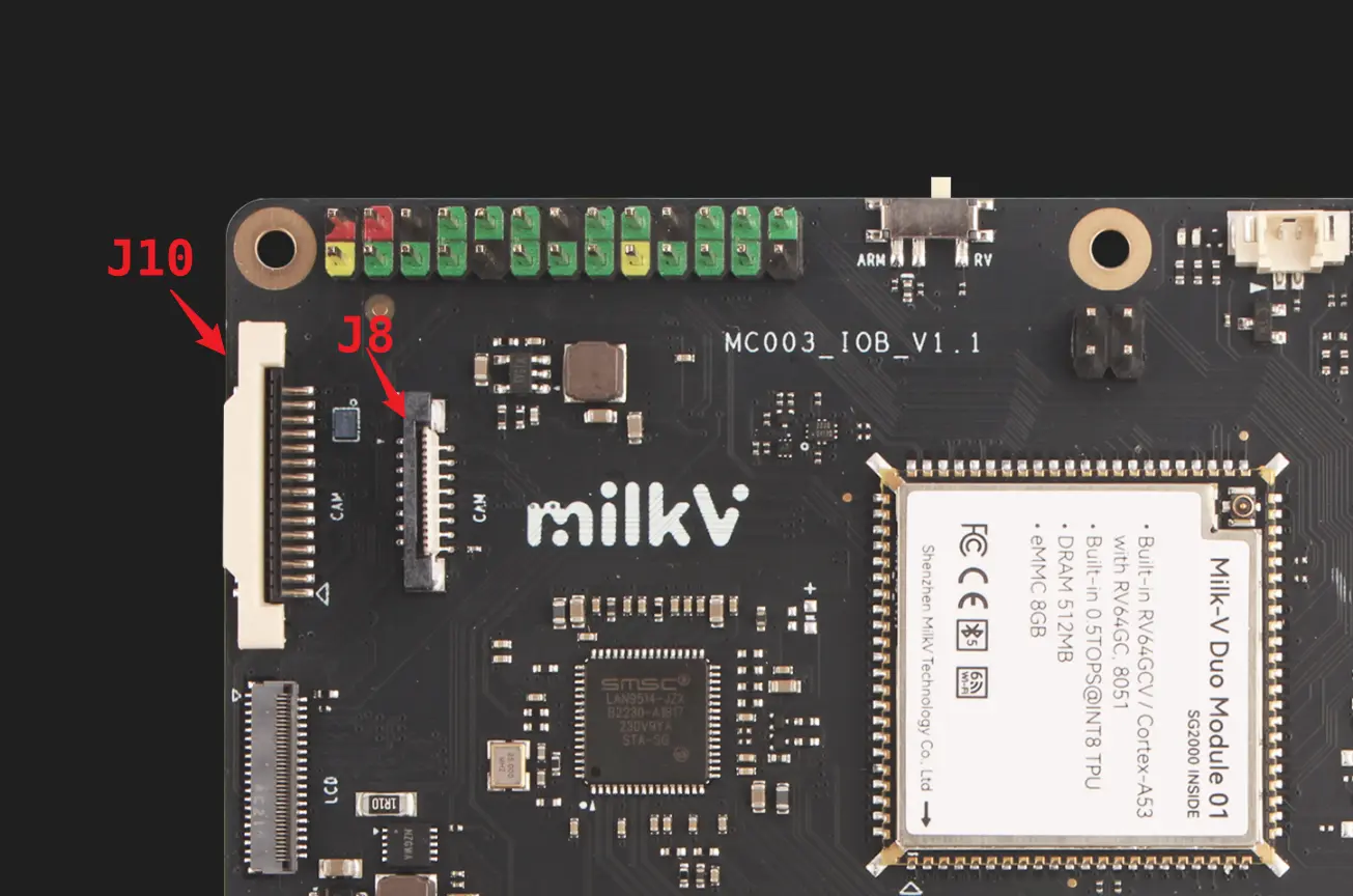
Note that the I2C used by the J1 interface is I2C3, and the I2C used by the J2 interface is I2C2. Please check the pin multiplexing configuration when using it.
J8 Connector FPC Definition
| J8 | Description |
|---|---|
| 1 | GND |
| 2 | MIPI0_DN0 |
| 3 | MIPI0_DP0 |
| 4 | GND |
| 5 | MIPI0_DN1 |
| 6 | MIPI0_DP1 |
| 7 | GND |
| 8 | MIPI0_CKN |
| 9 | MIPI0_CKP |
| 10 | GND |
| 11 | SENSOR_RSTN0 (1.8V) |
| 12 | SENSOR_CLK0 (1.8V) |
| 13 | I2C3_SCL (1.8V) |
| 14 | I2C3_SDA (1.8V) |
| 15 | |
| 16 | 3V3 |
J10 Connector FPC Definition
| J10 | Description |
|---|---|
| 1 | 3V3 |
| 2 | I2C2_SDA (3.3V) |
| 3 | I2C2_SCL (3.3V) |
| 4 | SENSOR_CLK1 (3.3V) |
| 5 | SENSOR_RSTN1 (3.3V) |
| 6 | GND |
| 7 | MIPI0_DP5 (CAM1_CP) |
| 8 | MIPI0_DN5 (CAM1_CN) |
| 9 | GND |
| 10 | MIPI0_DP4 (CAM1_DP1) |
| 11 | MIPI0_DN4 (CAM1_DN1) |
| 12 | GND |
| 13 | MIPI0_DP3 (CAM1_DP0) |
| 14 | MIPI0_DN3 (CAM1_DN0) |
| 15 | GND |
POE Header
| POE Pin | Description |
|---|---|
| 1 | VA- |
| 2 | VA+ |
| 3 | VB+ |
| 4 | VB- |
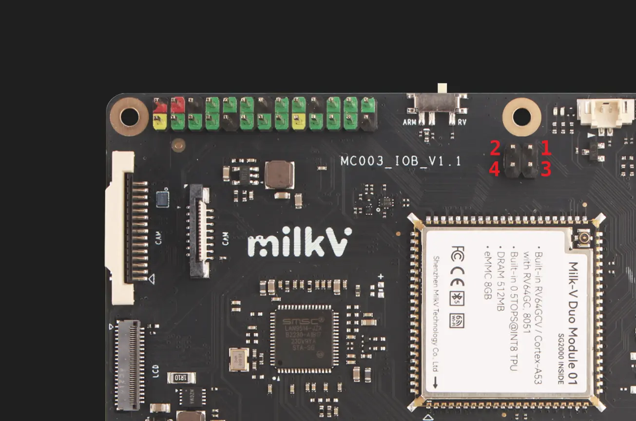
ADC Interfaces
| ADC Pin | Description |
|---|---|
| 1 | GND |
| 2 | 3V3 |
| 3 | 1V8 |
| 4 | ADC1 |
| 5 | ADC2 |
| 6 | ADC3 |
MIPI DSI Screen Interface
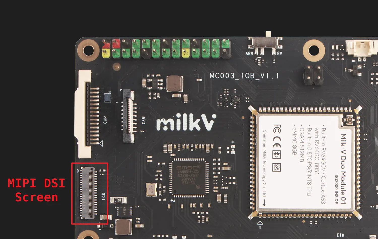
| LCD Pin | Description | Level |
|---|---|---|
| 1 | VDD3V3 | 3.3V |
| 2 | IOVCC1V8-3V3 | 1.8V |
| 3 | SENSOR-INT | |
| 4 | RESET | 1.8V |
| 5 | NC | |
| 6 | GND1 | |
| 7 | MIPI-0N | |
| 8 | MIPI-0P | |
| 9 | GND2 | |
| 10 | MIPI-1N | |
| 11 | MIPI-1P | |
| 12 | GND3 | |
| 13 | MIPI-CKN | |
| 14 | MIPI-CKP | |
| 15 | GND4 | |
| 16 | MIPI-2N | |
| 17 | MIPI-2P | |
| 18 | GND5 | |
| 19 | MIPI-3N | |
| 20 | MIPI-3P | |
| 21 | GND6 | |
| 22 | GND7 | |
| 23 | TP-RESET | 3.3V |
| 24 | TP-VCC | 3.3V |
| 25 | TP-INT | 3.3V |
| 26 | TP-SDA | 3.3V |
| 27 | TP-SCL | 3.3V |
| 28 | GND8 | |
| 29 | GND9 | |
| 30 | VCC3V31 | 3.3V |
| 31 | VCC3v32 | 3.3V |
| 32 | GND11 | |
| 33 | GND12 | |
| 34 | LED-1 | |
| 35 | LED- | |
| 36 | NC | |
| 37 | NC | |
| 38 | LED+1 | |
| 39 | LED+ |
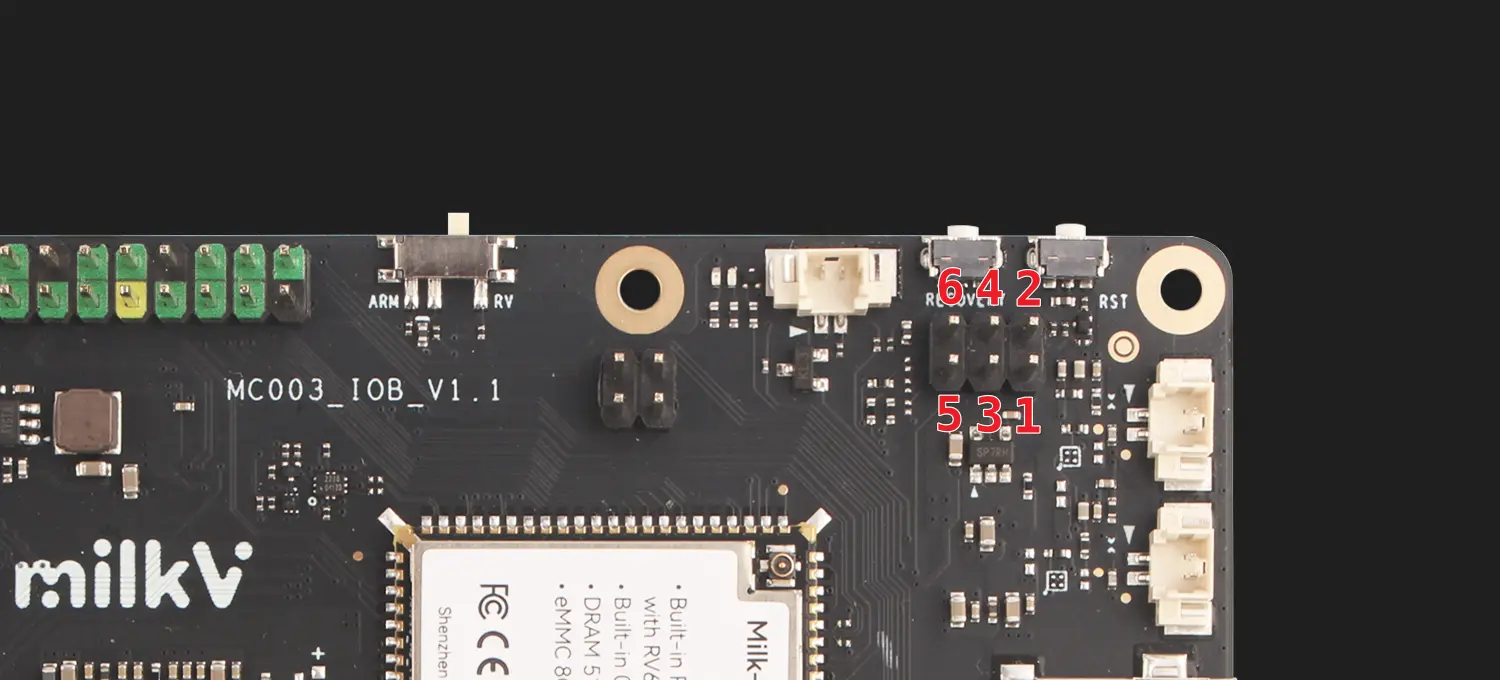
RTC Interface
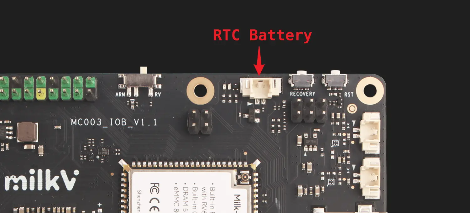
| ADC Pin | Description |
|---|---|
| 1 | GND |
| 2 | Vbat |
Audio Interfaces
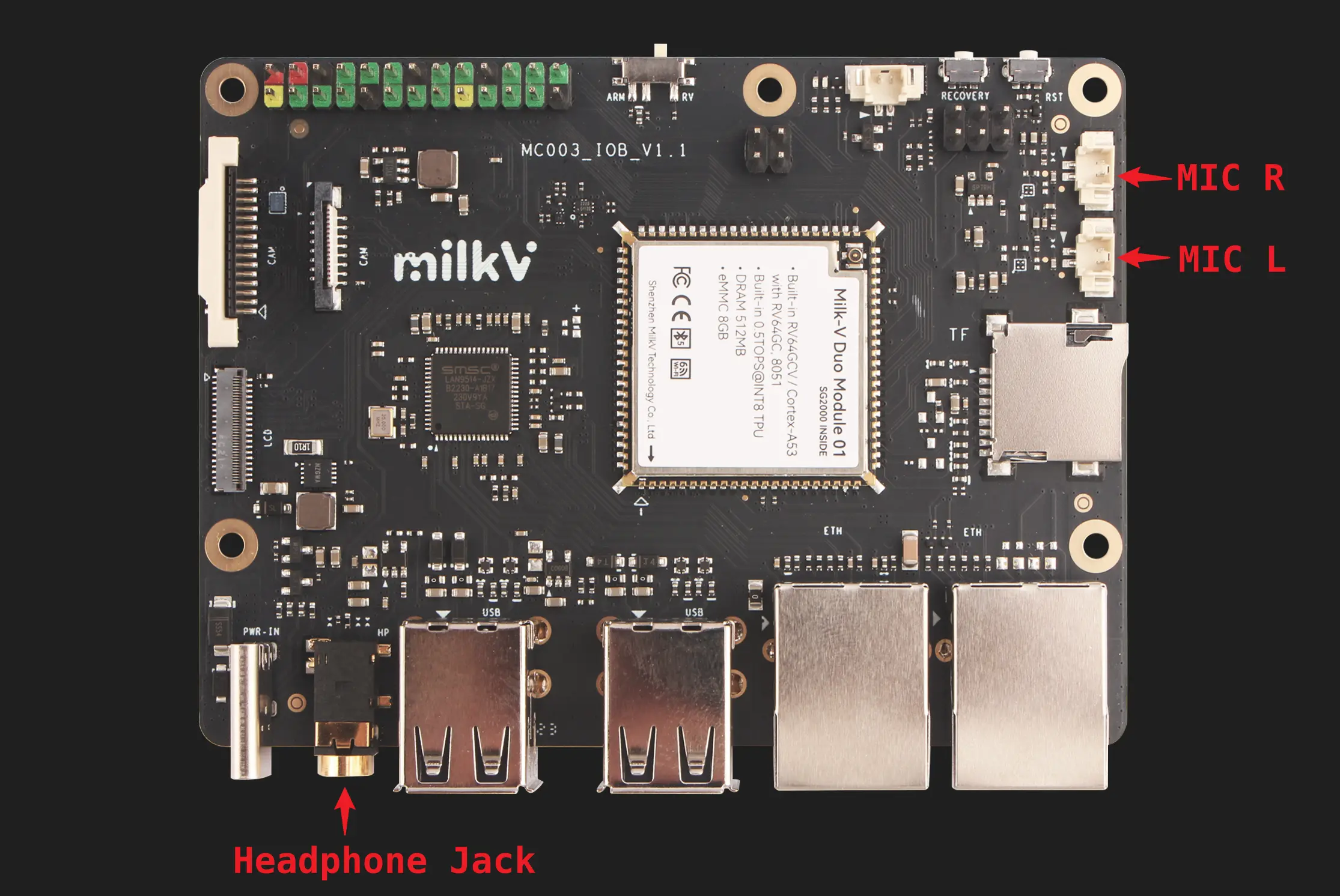
| MIC Pin | Description |
|---|---|
| 1 | MIC IN |
| 2 | GND |
Duo Module 01 EVB User Guide
RISC-V and ARM switching
The large core of Duo Module 01 EVB can choose to use RISC-V or ARM processor, which can be set through the switch on the board. If you find that Duo Module 01 EVB cannot start normally during use, please first check whether the switch is consistent with the firmware used.
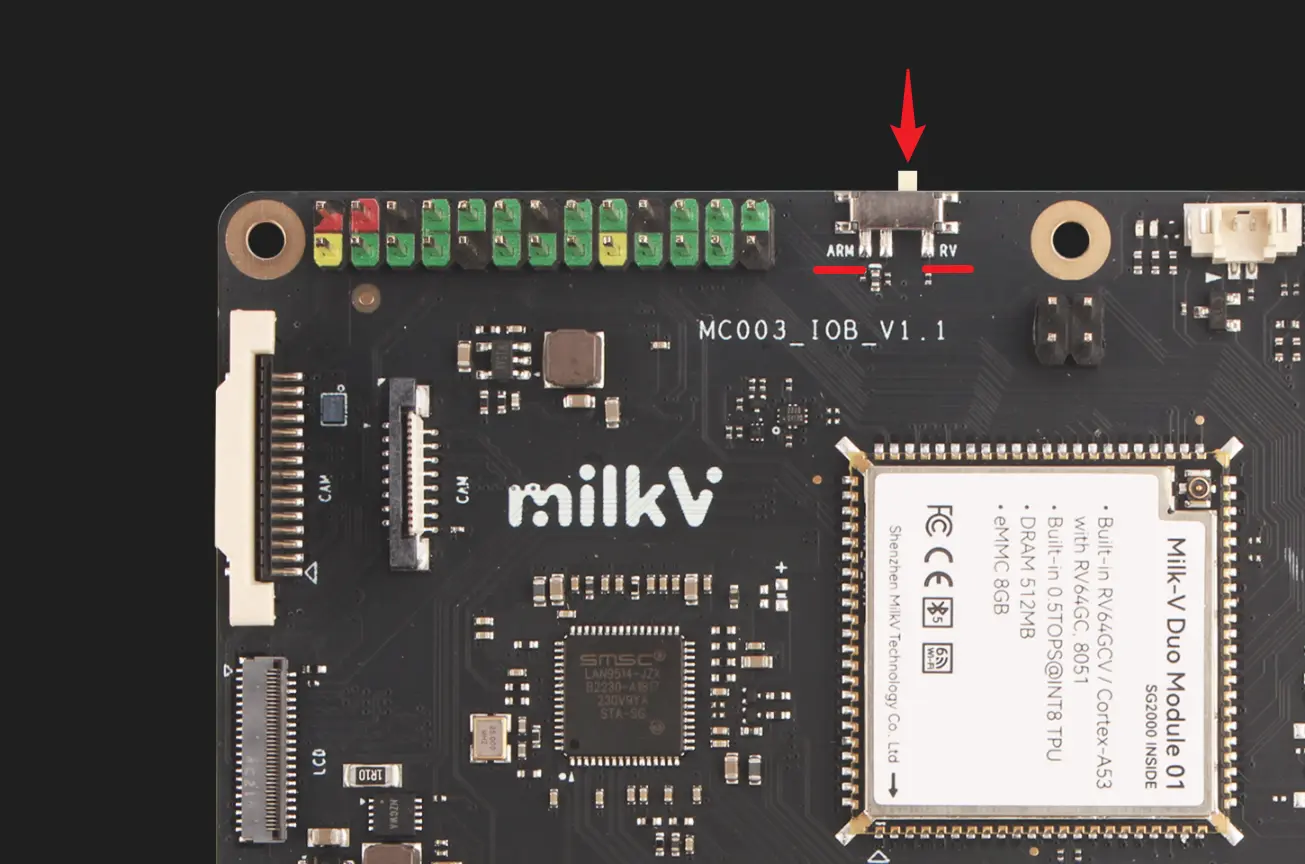
If the debug serial port is connected, you can see in the first line of the boot log that starting with C means starting from the RISC-V core, and starting with B means starting from the ARM core.
- RISC-V:
C.SCS/0/0.C.SCS/0/0.WD.URPL.USBI.USBW - ARM:
B.SCS/0/0.WD.URPL.B.SCS/0/0.WD.URPL.USBI.USBW
Usage of USB Type A interfaces
The USB functions of the EVB USB Type A interface and Type C interface are optional and cannot be used at the same time. The default firmware is configured with the USB network port (USB-NCM) function of the Type C port. If you need to switch to the USB 2.0 HOST port of the Type A port for use with USB flash drives and other devices, you need to execute the following command:
ln -sf /mnt/system/usb-host.sh /mnt/system/usb.sh
sync
Then execute the reboot command or power on again to make it take effect.
For example, after connecting a USB flash drive to the USB A port, you can use ls /dev/sd* to check whether the device is detected.
Mount it to the system to view the contents of the USB flash drive (take /dev/sda1 as an example):
mkdir /mnt/udisk
mount /dev/sda1 /mnt/udisk
Check whether the contents of the /mnt/udisk directory are as expected:
ls /mnt/udisk
Command to uninstall USB flash drive:
umount /mnt/udisk
When you want to restore the USB network (USB-NCM) function of the Type C port, execute:
rm /mnt/system/usb.sh
ln -sf /mnt/system/usb-ncm.sh /mnt/system/usb.sh
sync
Then execute the reboot command or power on again to make it take effect.
Duo Module 01 EVB has an onboard Ethernet interface, so the USB network port (USB-NCM) of the Type C port can be used without switching to the USB 2.0 Host function of the A port.
Fixed ethernet port MAC address
If you need to assign a fixed MAC address to the Ethernet port of EVB, please execute the following command:
Replace the MAC address in the command with the MAC address you want to set, and please note that MAC addresses of different devices within the same network segment must not be duplicated
echo "pre-up ifconfig eth0 hw ether 78:01:B3:FC:E8:55" >> /etc/network/interfaces && sync
then reboot the board.
UART Serial Console
Duo Module 01 EVB has a reserved UART debug serial port, which can be used to view the system startup log, or to log in to the console after the system starts and execute some terminal commands.
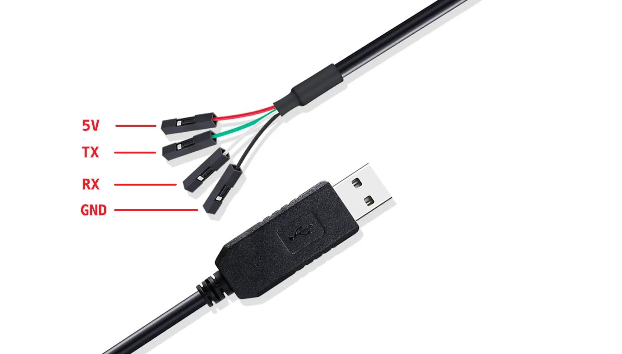
USB-TTL Serial Cable
The serial port level of Duo series is 3.3V.
The pin definitions of common USB to TTL serial cables are as follows:
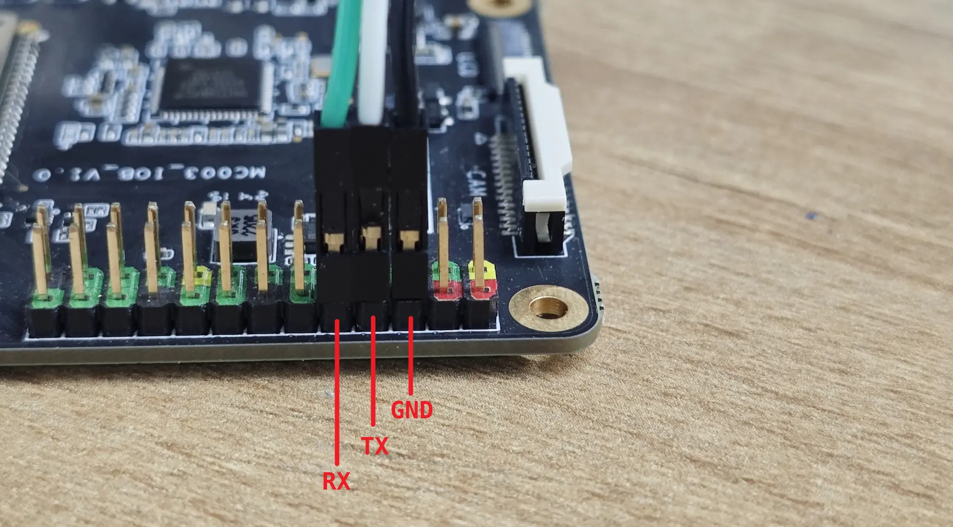
Connection
Connect the USB to TTL serial cable as shown below, leaving the red wire unconnected.
| Milk-V DouS | <---> | USB to TTL |
|---|---|---|
| GND (pin 6) | <---> | Black wire |
| TX (pin 8) | <---> | White wire |
| RX (pin 10) | <---> | Green wire |
The default serial port parameters of EVB are as follows:
baudrate: 115200
data bit: 8
stop bit: 1
parity  : none
flow control: none
WIFI configuration
Method 1
Edit the following file and replace ssid and psk with the WIFI account and password to be connected:
ctrl_interface=/var/run/wpa_supplicant
ap_scan=1
update_config=1

network={
  ssid="wifi_test"
  psk="12345678"
  key_mgmt=WPA-PSK
}
Then execute the following command:
wpa_supplicant -B -i wlan0 -c /etc/wpa_supplicant.conf
You can connect to WIFI. After connecting, you can view the assigned IP address through the ifconfig or ip a command.
If you need to automatically connect to the WIFI when booting, you can put the following command in the /mnt/system/auto.sh file.
interface="wlan0"
max_attempts=100
attempt=0
log_file="/var/log/auto.sh.log"

# Continuously attempt to detect if the interface exists, up to $max_attempts times
echo "start auto.sh" > "$log_file"
while [ $attempt -lt $max_attempts ]; do
    # Check if the wlan0 interface exists
    ip link show "$interface" > /dev/null 2>&1
    if [ $? -eq 0 ]; then
        echo "$(date +'%Y-%m-%d %H:%M:%S') $interface interface exists, starting wpa_supplicant..." >> "$log_file"
        wpa_supplicant -B -i "$interface" -c /etc/wpa_supplicant.conf >> "$log_file"
        break  # Exit the loop if the interface is found
    else
        echo "$(date +'%Y-%m-%d %H:%M:%S') $interface interface not found, waiting..." >> "$log_file"
        sleep 1  # Wait for 1 second before checking again
        attempt=$((attempt + 1))  # Increment the attempt counter
    fi
done

# If the maximum number of attempts is reached and the interface still not found, output an error message
if [ $attempt -eq $max_attempts ]; then
    echo "$(date +'%Y-%m-%d %H:%M:%S') Interface $interface not found after $max_attempts attempts" >> "$log_file"
fi
Fixed WIFI MAC address
Duo Module 01 EVB WIFI MAC address is randomly assigned. If you need to assign a fixed MAC address to the WIFI of EVB, please execute the following command::
Replace the MAC address in the command with the MAC address you want to set, and please note that MAC addresses of different devices within the same network segment must not be duplicated
echo "MAC_ADDR=11:22:33:44:55:66" > /mnt/system/firmware/aic8800/rwnx_settings.ini && sync
then reboot the board.
eMMC version firmware burning
The Duo Module 01 eMMC version does not have firmware burned and needs to be burned using a PC through the USB interface.
Use the USB burning tool under Windows to support eMMC. The firmware version is V1.1.2 or latest version.
Burning in Windows
-
Install driver
Download the USB driver installation tool: CviUsbDownloadInstallDriver.zip. After downloading, unzip and install.
-
Download burning tool
Download the command line burning tool under Windows CviBurn_v2.0_cli_windows.zip, unzip it after downloading.
-
Download firmware
The firmware of
Duo Module 01is common to that of DuoS. Download the latest version of DuoS eMMC firmware, currently milkv-duos-emmc-v1.1.2-2024-0801.zip, you can create a new rom folder in the burning toolCviBurn_v2.0_cli_windowsdirectory, and extract the downloaded eMMC firmware compressed package to rom directory, the directory structure of the burning tool is as follows:└───CviBurn_v2.0_cli_windows
│ cv_dl_magic.bin
│ usb_dl.exe
└───rom
│ boot.emmc
│ fip.bin
│ partition_emmc.xml
│ rootfs_ext4.emmc
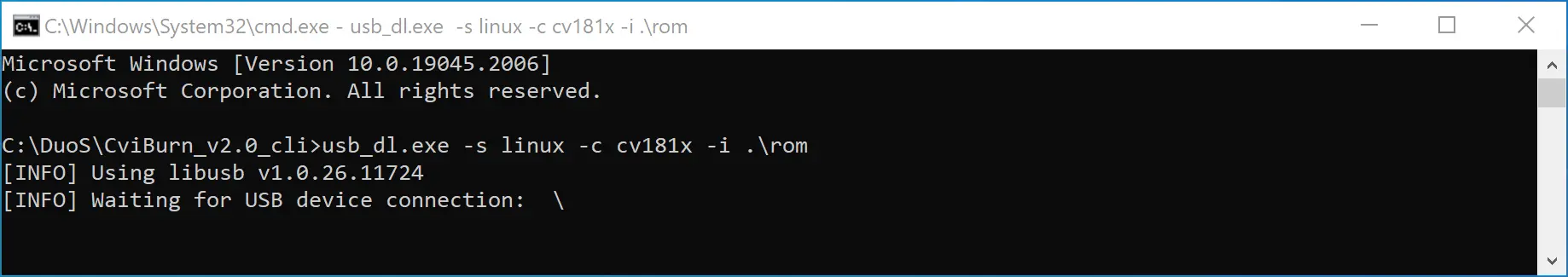
| ...In the Windows terminal, execute the burning command in the
CviBurn_v2.0_cli_windowsdirectory:.\usb_dl.exe -s linux -c cv181x -i .\rom*You can also put the firmware in other directories and specify the corresponding directory through the -i parameter in the command. *
Displays message waiting for USB connection:
Use Type-C data cable to connect EVB and PC (note, if EVB currently has an SD card inserted, please remove the SD card first), EVB will automatically power on and enter the burning mode, and the PC will display the burning status in real time. Recording progress:
[INFO] Waiting for USB device connection: ---
[INFO] found usb device vid=0x3346 pid=0x1000
[INFO] downloading file: .\rom\boot.emmc
[INFO] CVI_USB_PROGRAM
[INFO] updated size: 3384664/213100824(1%)
[INFO] downloading file: .\rom\rootfs_ext4.emmc
[INFO] CVI_USB_PROGRAM
[INFO] updated size: 20161944/213100824(9%)
[INFO] CVI_USB_PROGRAM
[INFO] updated size: 36939224/213100824(17%)
[INFO] CVI_USB_PROGRAM
[INFO] updated size: 53716504/213100824(25%)
[INFO] CVI_USB_PROGRAM
[INFO] updated size: 70493784/213100824(33%)
[INFO] CVI_USB_PROGRAM
[INFO] updated size: 87271064/213100824(40%)
[INFO] CVI_USB_PROGRAM
[INFO] updated size: 104048344/213100824(48%)
[INFO] CVI_USB_PROGRAM
[INFO] updated size: 120825624/213100824(56%)
[INFO] CVI_USB_PROGRAM
[INFO] updated size: 137602904/213100824(64%)
[INFO] CVI_USB_PROGRAM
[INFO] updated size: 154380184/213100824(72%)
[INFO] CVI_USB_PROGRAM
[INFO] updated size: 171157464/213100824(80%)
[INFO] CVI_USB_PROGRAM
[INFO] updated size: 187934744/213100824(88%)
[INFO] CVI_USB_PROGRAM
[INFO] updated size: 204712024/213100824(96%)
[INFO] CVI_USB_PROGRAM
[INFO] updated size: 213100696/213100824(99%)
[INFO] USB download complete
After the burning is completed, the EVB will automatically restart. After booting, you will see the blue LED on the DuoS flashing, indicating that the system has started normally and the burning is successful.
eMMC Erase
If you need to restore the eMMC to its initial state, please refer to the following command to clear the eMMC data (please back up important files in the eMMC in advance):
- Unlock readonly
echo 0 > /sys/block/mmcblk0boot0/force_ro
echo 0 > /sys/block/mmcblk0boot1/force_ro - Erase
dd if=/dev/zero of=/dev/mmcblk0boot0 bs=1M count=4
dd if=/dev/zero of=/dev/mmcblk0boot1 bs=1M count=4
Hardware Docs
Others
https://github.com/milkv-duo/duo-files/tree/main/duo-module-01