简介
Arduino 是一个很流行的开源硬件平台,具有简洁性、易用性和开放性等优点。它提供了丰富的库函数和示例代码,使得即使对于没有编程经验的人来说,也能够快速上手。同时,Arduino 社区非常活跃,您可以轻松地获取到各种项目教程、文档和支持。
Milk-V Duo 系列已经支持 Arduino 开发,您可以直接使用 Arduino IDE,进行简单的配置后即可使用。
Duo 系列 CPU 采用大小核设计,Arduino 固件运行在小核中,大核负责与 Arduino IDE 通讯,接收 Arduino 固件并将其加载到小核中运行。同时,大核中的 Linux 系统也是正常运行的。
另外,Duo 系列开发板已经支持可视化编程软件 VISUINO,相关内容可以参考该章节:VISUINO。
一、环境配置
安装 Arduino IDE
Arduino IDE 支持 Windows、Linux、macOS 三种操作系统,根据您使用的系统到 Arduino官方网站 下载对应安装包进行安装,当前最新的版本为 2.3.2,建议使用最新版本。
Arduino IDE 中添加 Duo 开发板
打开 Arduino IDE,在 文件 菜单中选择 首选项,在 设置 标签中的 其他开发板管理器地址 内添加 Duo 的配置文件地址:
https://github.com/kubuds/sophgo-arduino/releases/download/v0.2.5/package_sg200x_index.json
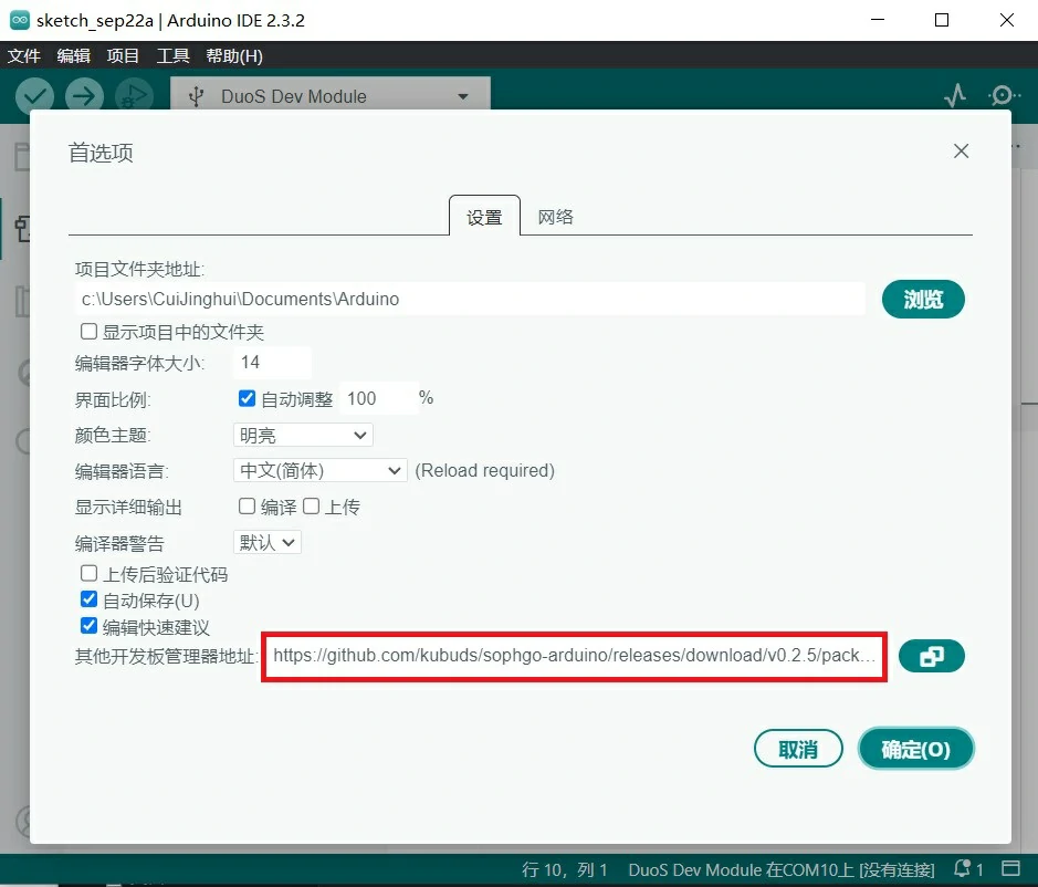
如果之前有配置其他开发板地址,用逗号隔开,或者点地址栏右侧的图标调出窗口,按提示添加。
配置好之后在 工具 菜单中选择 开发板,打开 开发板管理器,搜索 SG200X,点击 安装。
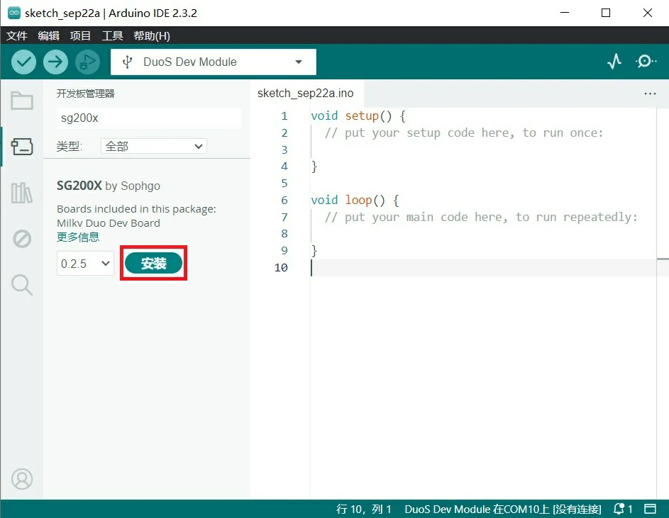
到此 Arduino IDE 中 Duo 的开发环境已安装完成,下面就可以进行代码编写测试了。
在 Duo 中测试点亮板载 LED
目前,Duo 的 SD 卡系统需要烧录支持 Arduino 的固件,请在 最新 Release 的固件中下载前缀为 arduino 的固件。
目前最新的可用 Arduino 固件版本为 Duo-V1.1.2。
DuoS 暂时没有提供直接可用的 Arduino 版本固件,请移步 Buildroot SDK ,克隆并切换到 arduino 分支进行编译。
参考前面章节中的 启动 Duo 安装好系统。
使用 USB 线将 Duo 连接到电脑,Duo 会自动上电开机。
Duo 的默认固件大核 Linux 系统会控制板载 LED 闪烁,这个是通过开机脚本实现的,我们现在要用小核 Arduino 来点亮 LED,需要将大核 Linux 中 LED 闪烁的脚本禁用,在 Duo 的终端中执行:
mv /mnt/system/blink.sh /mnt/system/blink.sh_backup && sync
也就是将 LED 闪烁脚本改名,重启 Duo 后,LED 就不会闪烁了:
reboot
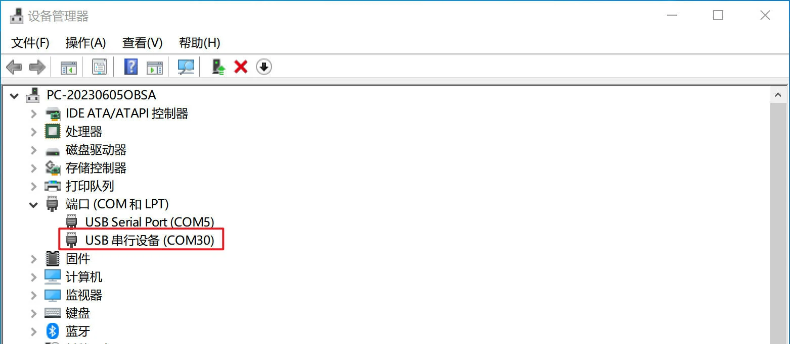
此时查看电脑的 设备管理器 的 端口 中会多出一个串口设备:
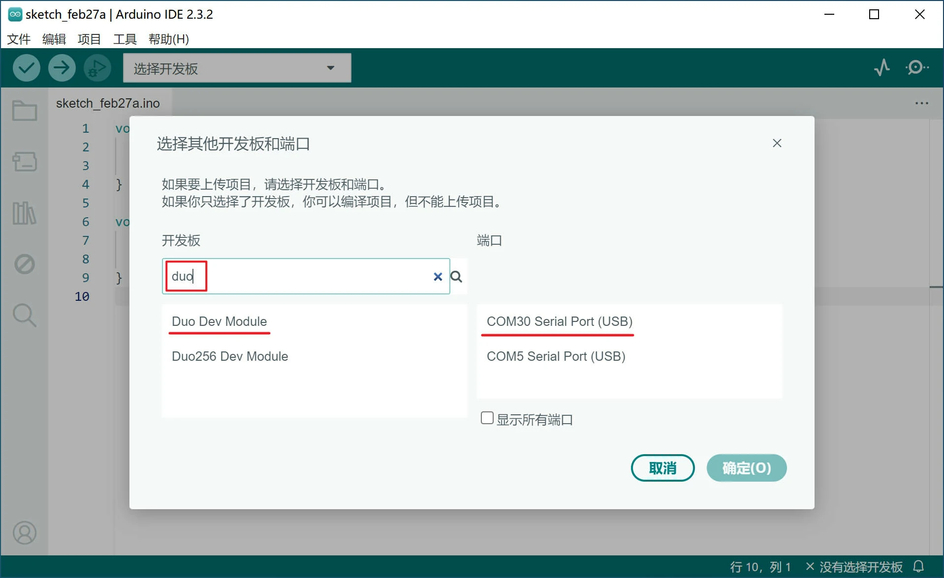
在 Arduino IDE 主界面点击 选择开发板,再点击 选择其他开发板和接口......
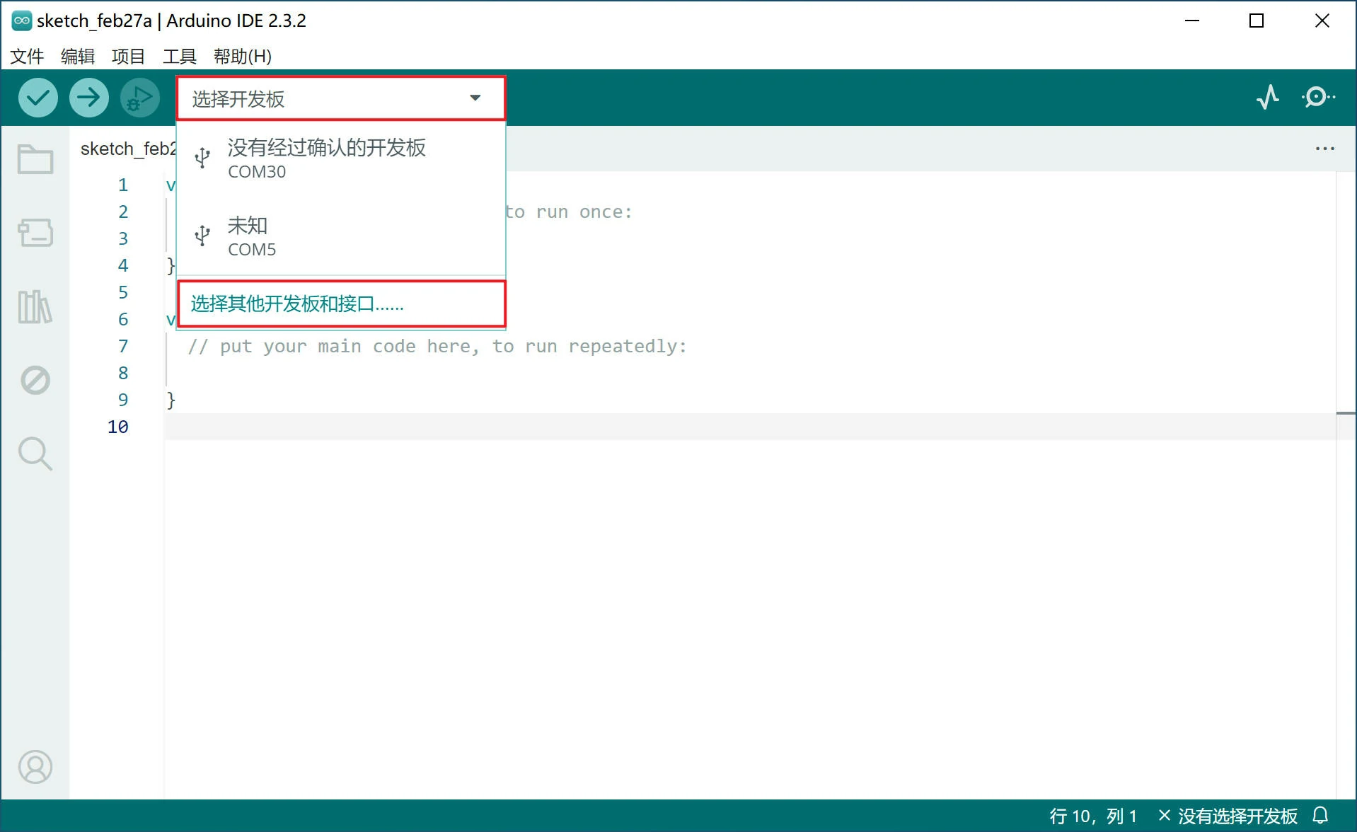
搜索 "duo",Duo 选择 Duo Dev Module,Duo256M 选择 Duo256 Dev Module,端口中选择对应的串口后点确定。
在 Arduino IDE 的 文件 菜单中依次打开 示例 > 01.Basics > Blink 测试程序,该程序功能实现的是 Arduino 设备板载 LED 闪烁,Duo 中也是支持的,您也许需要安装 pyserial 来支持上传功能,之后我们直接点 上传 按钮进行测试:
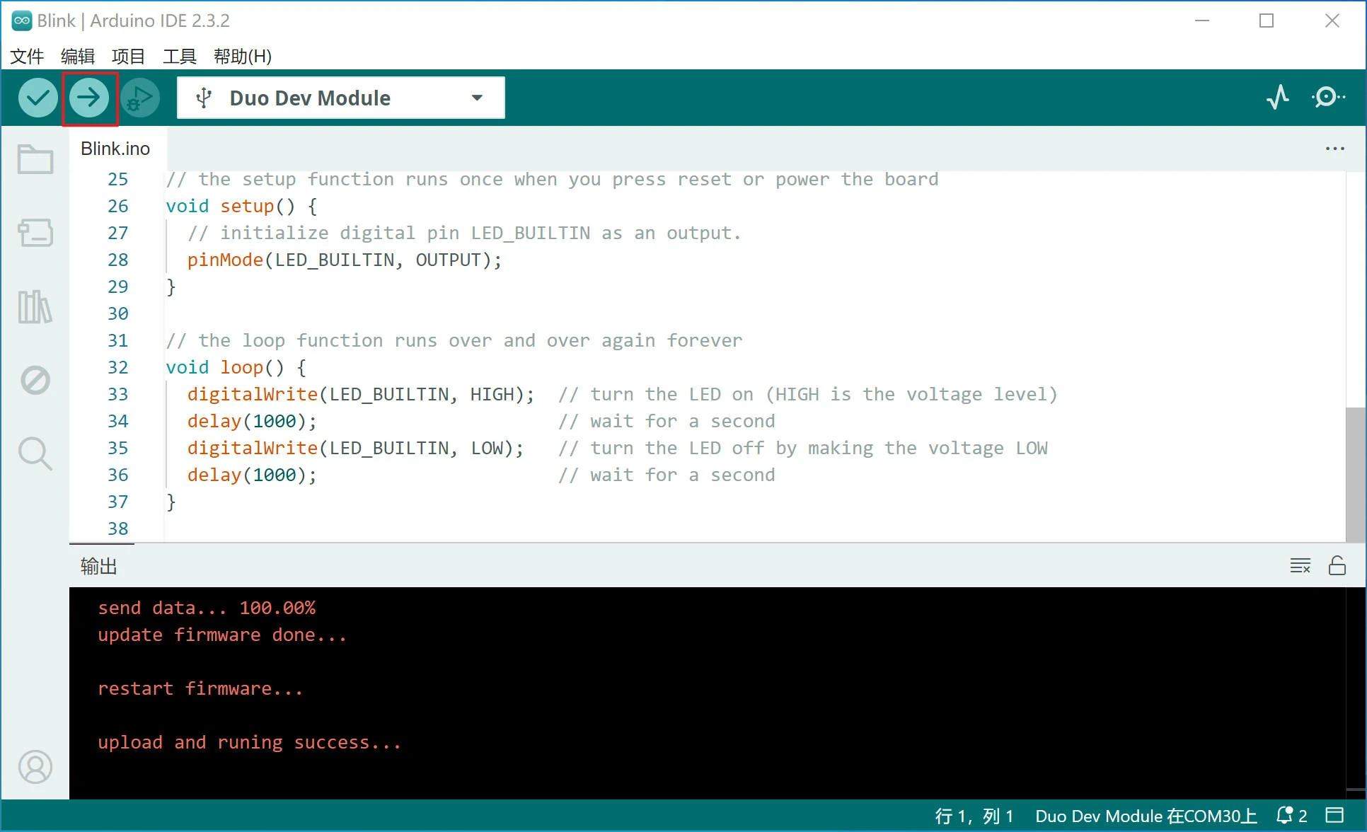
此时,可以看到 Duo 板载的 LED 间隔1秒闪烁。
在编译下载代码之前,请确保您的计算机中安装了 python 环境,并正确的配置了环境变量,缺少 python 环境可能造成代码无法编译和下载。
若您无法下载固件到开发��板,请您首先检查 pyserial 是否安装,若没有安装,您可以执行 pip install pyserial 来安装。
若您在安装 pyserial 后仍不能将代码上传到开发板,请检查您的计算机中是否安装了 serial ,同时安装 pyserial 和 serial 可能造成固件无法下载,请您执行 pip uninstall serial 将 serial 卸载。
二、Duo Arduino 引脚资源分配
Duo
| SPI | PWM | I2C | UART | GPIO | NAME | PIN | PIN | NAME | GPIO | ADC |
|---|---|---|---|---|---|---|---|---|---|---|
| I2C0_SCL | 1 | GP0 | 1 | 40 | VBUS | |||||
| I2C0_SDA | 2 | GP1 | 2 | 39 | VSYS | |||||
| GND | 3 | 38 | GND | |||||||
| PWM10 | GP2 | 4 | 37 | 3V3_EN | ||||||
| PWM11 | GP3 | 5 | 36 | 3V3(OUT) | ||||||
| PWM5 | UART3_TX | GP4 | 6 | 35 | ||||||
| PWM6 | UART3_RX | GP5 | 7 | 34 | ||||||
| GND | 8 | 33 | GND | |||||||
| SPI2_SCK | PWM9 | GP6 | 9 | 32 | GP27 | |||||
| SPI2_MOSI | PWM8 | GP7 | 10 | 31 | GP26 | ADC1 | ||||
| SPI2_MISO | PWM7 | I2C1_SDA | GP8 | 11 | 30 | RUN | ||||
| SPI2_CSn | PWM4 | I2C1_SCL | GP9 | 12 | 29 | GP22 | ||||
| GND | 13 | 28 | GND | |||||||
| 14 | GP10 | 14 | 27 | GP21 | 27 | |||||
| 15 | GP11 | 15 | 26 | GP20 | 26 | |||||
| PWM4 | GP12 | 16 | 25 | GP19 | 25 | |||||
| PWM5 | GP13 | 17 | 24 | GP18 | 24 | |||||
| GND | 18 | 23 | GND | |||||||
| 19 | GP14 | 19 | 22 | GP17 | 22 | |||||
| 20 | GP15 | 20 | 21 | GP16 | 21 | |||||
| 0 | LED |
Duo256M
| SPI | PWM | I2C | UART | GPIO | NAME | PIN | PIN | NAME | GPIO | ADC |
|---|---|---|---|---|---|---|---|---|---|---|
| 1 | GP0 | 1 | 40 | VBUS | ||||||
| 2 | GP1 | 2 | 39 | VSYS | ||||||
| GND | 3 | 38 | GND | |||||||
| PWM7 | GP2 | 4 | 37 | 3V3_EN | ||||||
| PWM6 | GP3 | 5 | 36 | 3V3(OUT) | ||||||
| PWM5 | UART3_TX | GP4 | 6 | 35 | ||||||
| PWM6 | UART3_RX | GP5 | 7 | 34 | ||||||
| GND | 8 | 33 | GND | |||||||
| SPI2_SCK | PWM9 | I2C3_SDA | GP6 | 9 | 32 | GP27 | ||||
| SPI2_MOSI | PWM8 | I2C3_SCL | GP7 | 10 | 31 | GP26 | ADC1 | |||
| SPI2_MISO | PWM7 | I2C1_SDA | GP8 | 11 | 30 | RUN | ||||
| SPI2_CSn | PWM4 | I2C1_SCL | GP9 | 12 | 29 | GP22 | ||||
| GND | 13 | 28 | GND | |||||||
| PWM10 | I2C2_SDA | 14 | GP10 | 14 | 27 | GP21 | 27 | |||
| PWM11 | I2C2_SCL | 15 | GP11 | 15 | 26 | GP20 | 26 | |||
| PWM4 | GP12 | 16 | 25 | GP19 | 25 | |||||
| PWM5 | GP13 | 17 | 24 | GP18 | 24 | |||||
| GND | 18 | 23 | GND | |||||||
| 19 | GP14 | 19 | 22 | GP17 | 22 | |||||
| 20 | GP15 | 20 | 21 | GP16 | 21 | |||||
| 0 | LED |
DuoS
排针 J3( RJ45 网口同侧)上的 GPIO 使用 3.3V 逻辑电平。
| SPI | PWM | I2C | UART | NUM | SG2000 | NAME | PIN | PIN | NAME | SG2000 | NUM | UART | PWM | SPI | JTAG |
|---|---|---|---|---|---|---|---|---|---|---|---|---|---|---|---|
| 3V3 | 1 | 2 | VSYS(5V) | ||||||||||||
| PWM3 | I2C4_SCL | 468 | XGPIOB[20] | B20 | 3 | 4 | VSYS(5V) | ||||||||
| I2C4_SDA | 469 | XGPIOB[21] | B21 | 5 | 6 | GND | |||||||||
| I2C1_SCL | 466 | XGPIOB[18] | B18 | 7 | 8 | A16 | XGPIOA[16] | 496 | UART0_TX/UART1_TX | PWM4 | |||||
| GND* | 9 | 10 | A17 | XGPIOA[17] | 497 | UART0_RX/UART1_RX | PWM5 | ||||||||
| PWM1 | I2C1_SDA | UART2_TX | 459 | XGPIOB[11] | B11 | 11 | 12 | B19 | XGPIOB[19] | 467 | UART2_TX | PWM2 | |||
| PWM2 | I2C1_SCL | UART2_RX | 460 | XGPIOB[12] | B12 | 13 | 14 | GND | |||||||
| UART2_RX | 470 | XGPIOB[22] | B22 | 15 | 16 | A20 | XGPIOA[20] | 500 | JTAG_TRST | ||||||
| 3V3 | 17 | 18 | A19 | XGPIOA[19] | 499 | UART1_TX/UART1_RTS | PWM7 | JTAG_TMS | |||||||
| SPI3_SDO | PWM3 | I2C2_SCL | 461 | XGPIOB[13] | B13 | 19 | 20 | GND | |||||||
| SPI3_SDI | I2C2_SDA | 462 | XGPIOB[14] | B14 | 21 | 22 | A18 | XGPIOA[18] | 498 | UART1_RX/UART1_CTS | PWM6 | JTAG_TCK | |||
| SPI3_SCK | UART2_TX | 463 | XGPIOB[15] | B15 | 23 | 24 | B16 | XGPIOB[16] | 464 | UART2_RX | SPI3_CS | ||||
| GND | 25 | 26 | A28 | XGPIOA[28] | 508 | UART2_TX/UART1_TX |
GND*:引脚 9 在 V1.1 版本硬件中是一个低电平的 GPIO,在 V1.2 及更高版本硬件中为 GND。
注意:CSI 摄像�头连接器 J2 上的 I2C 为 I2C2,所以在使用 J2 上的 CSI 摄像头时,J3 排针中的 I2C2 不可用。
排针 J4( USB-A 同侧) 上的 GPIO 使用 1.8V 逻辑电平。
| PWM | I2C | UART | MIPI DSI | NUM | SG2000 | NAME | PIN | PIN | NAME | SG2000 | NUM | MIPI DSI |
|---|---|---|---|---|---|---|---|---|---|---|---|---|
| VSYS(5V) | 52 | 51 | AUDIO_OUT_R | |||||||||
| PWM12 | I2C4_SCL | UART3_TX | 449 | XGPIOB[1] | B1 | 50 | 49 | AUDIO_OUT_L | ||||
| PWM13 | I2C4_SDA | UART3_RX | 450 | XGPIOB[2] | B2 | 48 | 47 | AUDIO_IN_R | ||||
| 451 | XGPIOB[3] | B3 | 46 | 45 | AUDIO_IN_L | |||||||
| PWM10 | I2C2_SDA | LCD_RST | 354 | PWR_GPIO[2] | E2 | 44 | 43 | 3V3 | ||||
| PWM9 | I2C2_SCL | UART2_RX | LCD_PWR_CT | 353 | PWR_GPIO[1] | E1 | 42 | 41 | C18 | XGPIOC[18] | 434 | MIPI_TX_3N |
| PWM8 | UART2_TX | LCD_PWM | 352 | PWR_GPIO[0] | E0 | 40 | 39 | C19 | XGPIOC[19] | 435 | MIPI_TX_3P | |
| GND | 38 | 37 | GND | |||||||||
| MIPI_TX_2N | 436 | XGPIOC[20] | C20 | 36 | 35 | C16 | XGPIOC[16] | 432 | MIPI_TX_CN | |||
| MIPI_TX_2P | 437 | XGPIOC[21] | C21 | 34 | 33 | C17 | XGPIOC[17] | 433 | MIPI_TX_CP | |||
| GND | 32 | 31 | GND | |||||||||
| MIPI_TX_1N | 430 | XGPIOC[14] | C14 | 30 | 29 | C12 | XGPIOC[12] | 428 | MIPI_TX_0N | |||
| MIPI_TX_1P | 431 | XGPIOC[15] | C15 | 28 | 27 | C13 | XGPIOC[13] | 429 | MIPI_TX_0P |
在 DuoS 中, SPI、I2C1/2、ADC 暂时不可用,请您等待后续软件更新。
三、代码示例
GPIO 使用示例
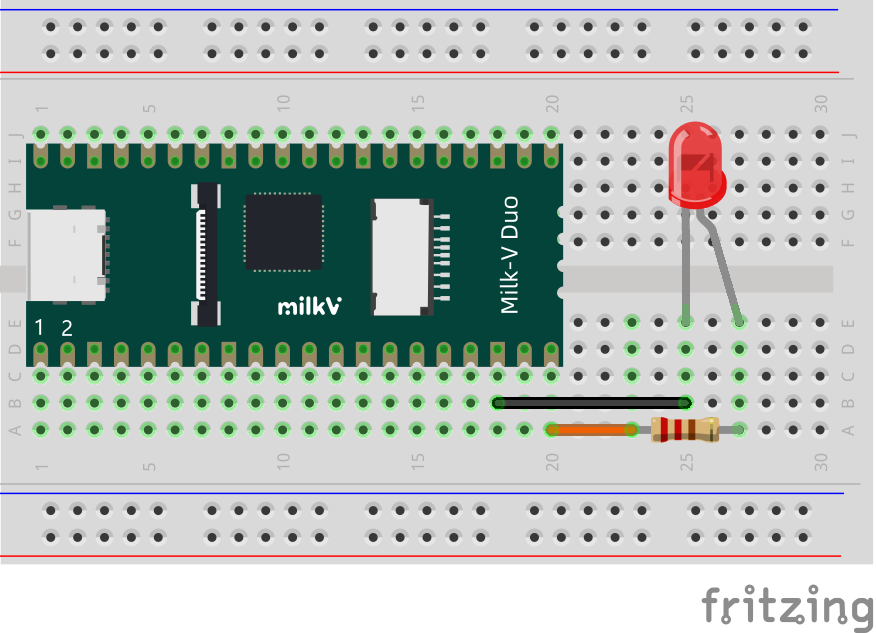
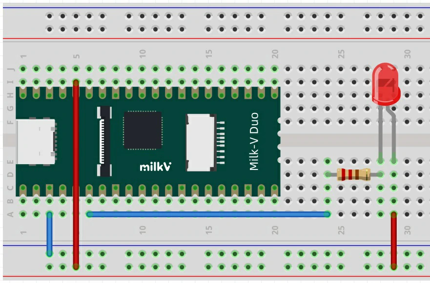
该程序实现将 Duo 物理引脚 20 间隔1秒循环输出高低电平,通过外接 LED 来观察现象。
连接方法如下,LED 负极接 Duo 的地(比如引脚18),正极串接一个 1K 电阻后,连接到引脚20:
测试程序:
#define TEST_PIN 20  //0,1,2,14,15,19,20,21,22,24,25,26,27

// the setup function runs once when you press reset or power the board
void setup() {
  pinMode(TEST_PIN, OUTPUT);
}

// the loop function runs over and over again forever
void loop() {
  digitalWrite(TEST_PIN, HIGH); // turn the TEST_PIN on (HIGH is the voltage level)
  delay(1000);                  // wait for a second
  digitalWrite(TEST_PIN, LOW);  // turn the TEST_PIN off by making the voltage LOW
  delay(1000);                  // wait for a second
}
- 如果不接 LED,可以通过万用表或示波器观察引脚的状态变化。
- TEST_PIN 配置为 0 可以测试 Duo 板载 LED。
UART 使用示例
串口输出
UART 串口默认使用的是物理引脚 6/7 上的 UART3,在调试 Arduino 程序时,可以通过该串口打印调试信息。
如果您使用的是 DuoS 开发板,UART3 默认映射到 50/48 引脚。因为 50/48 引脚使用 1.8V 电平,可能造成使用上不方便,建议您使用 UART2 代替。
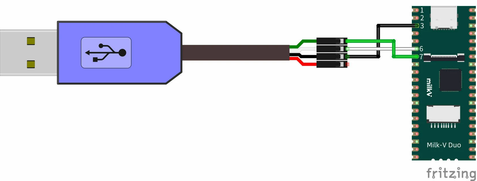
连接方法如下,电脑端可使用 USB 转 TTL 串口线,逻辑电平为 3.3V,波特率为 115200,串口线的 RX 连接 Duo 的 UART3_TX,串口线的 TX 连接 Duo 的 UART3_RX,串口线的 GND 连接 Duo 的任意 GND 比如引脚 3:
测试程序:
void setup() {
  Serial.begin(115200);
}

void loop() {
  Serial.printf("hello world\r\n");
  delay(1000);
}
运行后可以在电脑串口工具看到间隔1秒打印"hello world"字符串:
hello world
hello world
另外,该默认串口使用的是 Duo 的 UART3 接口,所以程序中也可以使用 Serial3:
void setup() {
  Serial3.begin(115200);
}

void loop() {
  Serial3.printf("hello world\r\n");
  delay(1000);
}
I2C 使用示例
Duo、Duo256M 和 DuoS 的 I2C 接口资源不同,需对照前面的引脚分配图来使用。
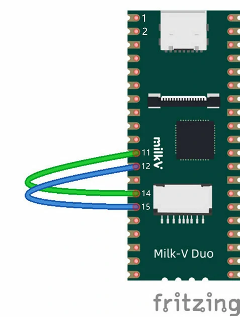
I2C0 向 I2C1 发送数据 (Duo)
硬件连接如下,将 I2C0 和 I2C1 的 SDA 和 SCL 引脚对应连接,再按上述 UART 示例中的方法连接串口到电脑上查看打印信息。

Duo 中 Wire 函数默认映射为 I2C0,也就是 Wire 等价与 Wire0。
测试代码:
#include <Wire.h>

void receive(int a) {
  Serial.printf("receive %d bytes\n\r", a);
  while(a--) {
    Serial.printf("%d \n\r", Wire1.read());
  }
}

void setup() {
  Serial.begin(115200);

  Wire1.begin(0x50);
  Wire1.onReceive(receive);

  Wire.begin();
  Serial.printf("test slave\n\r");
  Wire1.print();
}

byte val = 0;

void loop() {
  Wire.beginTransmission(0x50);         // Transmit to device number 0x50
  Serial.printf("send %d \n\r", ++val);
  Wire.write(val);                      // Sends value byte
  Wire.endTransmission();               // Stop transmitting
  Wire1.onService();
  delay(1000);
}
测试结果:
test slave
Wire1: 1
[iic_dump_register]: ===dump start
IC_CON = 0x22
IC_TAR = 0x55
IC_SAR = 0x50
IC_SS_SCL_HCNT = 0x1ab
IC_SS_SCL_LCNT = 0x1f3
IC_ENABLE = 0x1
IC_STATUS = 0x6
IC_INTR_MASK = 0x224
IC_INTR_STAT = 0
IC_RAW_INTR_STAT = 0x10
[iic_dump_register]: ===dump end
send 1
receive 1 bytes
1
send 2
receive 1 bytes
2
send 3
receive 1 bytes
3
send 4
receive 1 bytes
4
I2C1 向 I2C2 发送数据 (Duo256M)
注意,Duo256M 没有 I2C0。
硬件连接如下,将 I2C1 和 I2C2 的 SDA 和 SCL 引脚对应连接,再按上述 UART 示例中的方法连接串口到电脑上查看打印信息。
Duo256M 中 Wire 函数默认映射为 I2C1,也就是 Wire 等价与 Wire1。
测试代码:
#include <Wire.h>

void receive(int a) {
  Serial.printf("receive %d bytes\n\r", a);
  while(a--) {
    Serial.printf("%d \n\r", Wire2.read());
  }
}

void setup() {
  Serial.begin(115200);

  Wire2.begin(0x50);
  Wire2.onReceive(receive);

  Wire.begin();
  Serial.printf("test slave\n\r");
  Wire2.print();
}

byte val = 0;

void loop() {
  Wire.beginTransmission(0x50);         // Transmit to device number 0x50
  Serial.printf("send %d \n\r", ++val);
  Wire.write(val);                      // Sends value byte
  Wire.endTransmission();               // Stop transmitting
  Wire2.onService();
  delay(1000);
}
测试结果:
test slave
Wire2: 1
[iic_dump_register]: ===dump start
IC_CON = 0x22
IC_TAR = 0x55
IC_SAR = 0x50
IC_SS_SCL_HCNT = 0x1ab
IC_SS_SCL_LCNT = 0x1f3
IC_ENABLE = 0x1
IC_STATUS = 0x6
IC_INTR_MASK = 0x224
IC_INTR_STAT = 0
IC_RAW_INTR_STAT = 0x10
[iic_dump_register]: ===dump end
send 1
receive 1 bytes
1
send 2
receive 1 bytes
2
send 3
receive 1 bytes
3
send 4
receive 1 bytes
4
SPI 使用示例
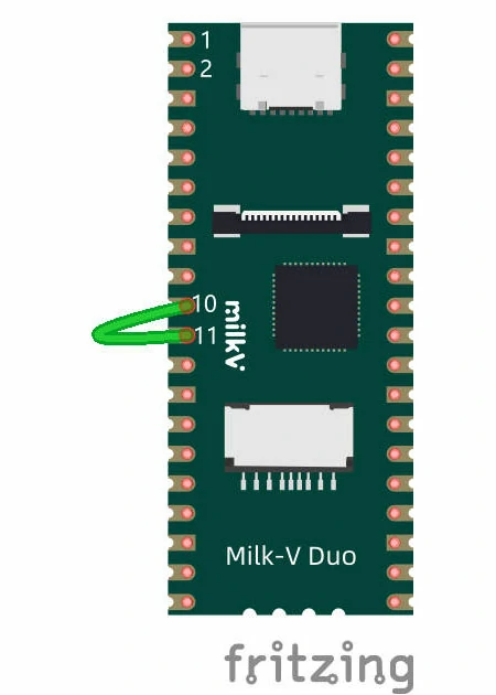
SPI 回环测试
硬件连接如下,将 SPI 的 MOSI 和 MISO 短接,也就是引脚 10 和引脚 11,再按上述 UART 示例中的方法连接串口到电脑上查看打印信息。
测试代码:
#include <SPI.h>

char str[]="hello world\n";
void setup() {
  // put your setup code here, to run once:
  Serial.begin(115200);
  SPI.begin();
}

byte i = 0;

void loop() {
  // put your main code here, to run repeatedly:
  // digitalWrite(12, 1);
  SPI.beginTransaction(SPISettings());
  Serial.printf("transfer %c\n\r", str[i]);
  char out = SPI.transfer(str[i++]);        // spi loop back
  SPI.endTransaction();
  Serial.printf("receive %x \n\r", out);
  i %= 12;
}
运行结果:
receive a
transfer h
receive 68
transfer e
receive 65
transfer l
receive 6c
transfer l
receive 6c
transfer o
receive 6f
transfer
receive 20
transfer w
receive 77
transfer o
receive 6f
transfer r
receive 72
transfer l
receive 6c
transfer d
receive 64
transfer
PWM 使用示例
硬件连接如下,将 DUO 的 GP4 连接到 LED 负极。
测试代码:
void setup() {
  pinMode(6, OUTPUT);
}

void loop() {
  for(int i = 128; i < 255; i++)
  {
    analogWrite(6,i);
    delay(50);
  }
  for(int i = 255; i > 128; i--)
  {
    analogWrite(6,i);
    delay(50);
  }
}
编译并烧录后能观察到LED灯呼吸效果。
在使用 PWM 时请注意 PWM 资源的分配,同一个 PWM 可以被分配到两个不同引脚,但两个引脚输出是完全相同的。
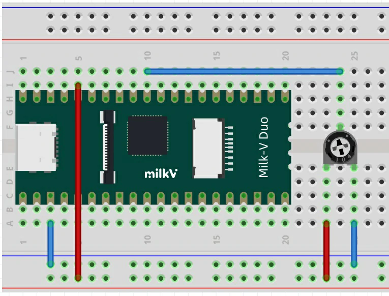
ADC 使用示例
硬件连接如下,将 DUO 的 GP26 连接到电位器信号脚,其他两脚分别连接电源正极和负极。
测试代码:
int adc_get_val = 0;

void setup() {
  pinMode(0,OUTPUT);
}

void loop() {
  adc_get_val = analogRead(31);

  digitalWrite(0,HIGH);
  delay(adc_get_val);
  digitalWrite(0,LOW);
  delay(adc_get_val);
}
编译并烧录后能观察到板载 LED 灯闪烁频率随电位器位置改变而改变。
MailBox 使用示例
将如下代码编译并烧录到小核 Arduino 中,这段程序能够从 MailBox 中读取大核发来的信息并打印到串口,串口接线请参考本章UART使用示例。
#include "mailbox.h"

struct valid_t {
  uint8_t linux_valid;
  uint8_t rtos_valid;
} __attribute__((packed));

typedef union resv_t {
  struct valid_t valid;
  unsigned short mstime;  // 0 : noblock, -1 : block infinite
} resv_t;

typedef struct cmdqu_t cmdqu_t;
/* cmdqu size should be 8 bytes because of mailbox buffer size */
struct cmdqu_t {
  uint8_t ip_id;
  uint8_t cmd_id : 7;
  uint8_t block : 1;
  union resv_t resv;
  unsigned int param_ptr;
} __attribute__((packed)) __attribute__((aligned(0x8)));

void showmsg(MailboxMsg msg) {
  cmdqu_t *cmdq;
  Serial.print("Get Msg: ");
  Serial.println(*(msg.data), HEX);
  cmdq = (cmdqu_t *)msg.data;
  Serial.printf("cmdq->ip_id = %d\r\n", cmdq->ip_id);
  Serial.printf("cmdq->cmd_id = %x\r\n", cmdq->cmd_id);
  Serial.printf("cmdq->block = %d\r\n", cmdq->block);
  Serial.printf("cmdq->para_ptr = %x\r\n", cmdq->param_ptr);
  *(msg.data) = 0;
}

void setup() {
  Serial.begin(115200);
  mailbox_init(false);
  mailbox_register(0, showmsg);
  mailbox_enable_receive(0);
  Serial.println("Mailbox Start");
}

void loop() {

}
编译测试程序 mailbox_test 并在大核 Linux 上运行,该测试程序已经存放在 duo-examples 仓库中,可以参考 README 进行编译。
运行后,大核 Linux 输出:
C906B: cmd.param_ptr = 0x2
C906B: cmd.param_ptr = 0x3
小核串口打印:
Mailbox Start
Get Msg: 19300
cmdq->ip_id = 0
cmdq->cmd_id = 13
cmdq->block = 1
cmdq->para_ptr = 2
Get Msg: 19300
cmdq->ip_id = 0
cmdq->cmd_id = 13
cmdq->block = 1
cmdq->para_ptr = 3
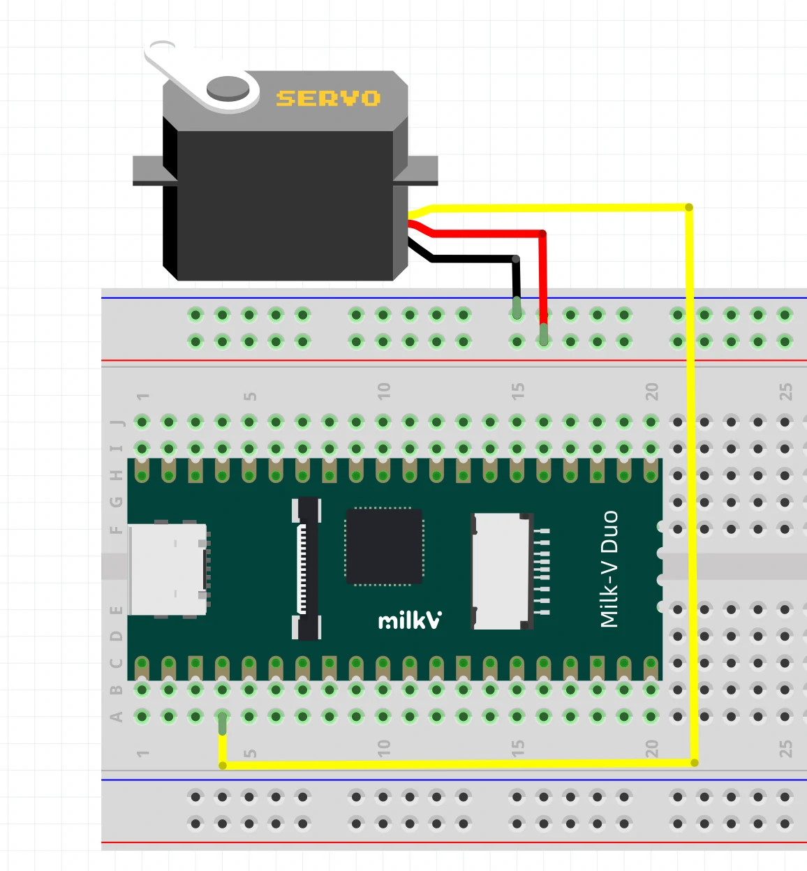
Servo 库 使用示例
首先请使用我们修改的 Servo 库 替换 Arduino 库目录中的 Servo 库,该库默认路径为 C:\Users\[您的用户名]\AppData\Local\Arduino15\libraries 。
以下测试代码您也可以在 Arduino-IDE 的菜单栏 File - Examples - Servo - Sweep 中找到,请您注意修改引脚号到带 PWM 功能的引脚上。
在烧录代码前,请您注意检查舵机是否正确连接到设定的引脚上。
#include <Servo.h>

Servo myservo;

int pos = 0;    // variable to store the servo position

void setup() {
  myservo.attach(4);  // attaches the servo on pin 4 to the Servo object
}

void loop() {
  for (pos = 0; pos <= 180; pos += 1) { // goes from 0 degrees to 180 degrees
    // in steps of 1 degree
    myservo.write(pos);              // tell servo to go to position in variable 'pos'
    delay(15);                       // waits 15 ms for the servo to reach the position
  }
  for (pos = 180; pos >= 0; pos -= 1) { // goes from 180 degrees to 0 degrees
    myservo.write(pos);              // tell servo to go to position in variable 'pos'
    delay(15);                       // waits 15 ms for the servo to reach the position
  }
}
程序烧录后,您可以观察到连接的舵机按周期来回摆动。
四、传感器示例
L9110H
L9110H_test 代码目录:https://github.com/milkv-duo/duo-arduino-examples/tree/master/L9110H_test
直流电机驱动芯片L9110H的示例代码,按照代码注释内容接好线后烧录运行,电机会按照逐渐加速和减速、反向逐渐加速和减速循环运行。
LCD1602
LCD1602_test 代码目录:https://github.com/milkv-duo/duo-arduino-examples/tree/master/LCD1602_test
LCD1602 I2C 接口屏幕的示例代码,按代码注释接好线后烧录运行,屏幕显示字符串。
LCD2004
LCD2004_test 代码目录:https://github.com/milkv-duo/duo-arduino-examples/tree/master/LCD2004_test
LCD2004 I2C 接口屏幕的示例代码,按代码注释接好线后烧录运行,屏幕显示字符串。
Buzzer
buzzer_test 代码目录:https://github.com/milkv-duo/duo-arduino-examples/tree/master/buzzer_test
蜂鸣器模块示例代码,按代码注释接线后烧录运行,蜂鸣器循环播放三种频率的蜂鸣声。
Buzzer Play Wave
buzzer_play_wave 代码目录:https://github.com/milkv-duo/duo-arduino-examples/tree/master/buzzer_play_wave
蜂鸣器模块示例代码,按代码注释接线后烧录运行,蜂鸣器首先播放 C 大调 1-7 七个音调,然后循环播放“两只老虎”。
HC-SR04
hc_sr04_test 代码目录:https://github.com/milkv-duo/duo-arduino-examples/tree/master/hc_sr04_test
HC-SR04 超声波测距传感器模块的示例代码,示例代码烧录运行后,开发板会向串口打印测量到的距离数据。
RC522
rc522_test 代码目录:https://github.com/milkv-duo/duo-arduino-examples/tree/master/rc522_test
RC522 RFID读写模块的示例代码,代码烧录运行后,开发板会循环检测是否读到ID卡,若检测到ID卡,则向串口打印卡片类型和卡号信息。
SSD1306
ssd1306_test 代码目录:https://github.com/milkv-duo/duo-arduino-examples/tree/master/ssd1306_test
SSD1306 OLED 屏幕模块的示例代码,按注释接线并烧录代码后,屏幕显示眼睛的动态动画。
五、Arduino APIs
Digital I/O
digitalWrite()
void digitalWrite(uint8_t pinNumber, uint8_t status)
指定引脚输出高或者低。
digitalRead()
int digitalRead(uint8_t pinNumber)
从指定的数字引脚读取值(高电平或低电平)。
pinMode()
void pinMode(uint8_t pinNumber, uint8_t pinMode)
配置指定的引脚作为输入或输出。
Analog I/O
analogRead()
uint32_t analogRead(uint32_t pinNumber)
从指定的模拟引脚(ADC)读取值。
analogReadResolution()
void analogReadResolution(int bits)
设置由 analogRead() 返回的值的大小(以 bit 为单位)。
analogWrite()
void analogWrite(uint8_t pinNumber, uint32_t val)
将模拟值(PWM)写入引脚。
analogWriteResolution()
void analogWriteResolution(int bits)
设置 analogWrite() 函数的分辨率。
Wire(I2C)
begin()
void begin(csi_iic_addr_mode_t addr_mode = IIC_ADDRESS_7BIT);
void begin(uint16_t address, csi_iic_addr_mode_t addr_mode = IIC_ADDRESS_7BIT);
beginTransmission()
void beginTransmission(uint16_t);
endTransmission()
uint8_t endTransmission(bool stopBit);
uint8_t endTransmission(void);
requestFrom()
size_t requestFrom(uint16_t address, size_t quantity, bool stopBit);
size_t requestFrom(uint16_t address, size_t quantity);
write()
size_t write(uint8_t data);
size_t write(const uint8_t * data, size_t quantity);
available()
virtual int available(void);
read()
virtual int read(void);
onReceive()
void onReceive(void(*)(int));
onRequest()
void onRequest(void(*)(void));
其他功能接口以及在 Duo 中的用法,后续会陆续更新,您也可以先参考 Arduino 官方文档。