Introduction
wiringX is a library that allows developers to control the GPIO of various platforms with generic and uniform functions. By using wiringX, the same code will run on all platforms supported by wiringX, natively.
This article will be divided into the following four parts to introduce how to develop applications on Duo using wiringX:
- Configuration of the application compilation environment based on wiringX
- Basic usage code demonstration
- Introduction to some demos and projects implemented using wiringX
- wiringX APIs
If you are already familiar with the usage of wiringX, you can directly refer to our sample code: duo-examples.
Please note that many pin functions of the Duo series are multiplexed. When using wiringX to control the functions of each pin, it is important to confirm the current state of the pin to ensure it matches the desired functionality. If it doesn't, you can use the duo-pinmux command to switch it to the desired function.
Please refer to the detailed usage instructions for more information:pinmux.
Duo series wiringX pin numbers
Duo/Duo256M
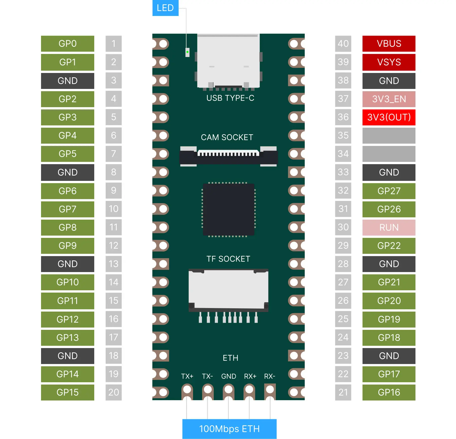
The wiringX pin numbers of Duo and Duo256M are consistent with the pin name numbers. However, the blue LED control pin is not available on the 40-pin physical pinout, and its wiringX pin number is 25.
| wiringX | PIN NAME | Pin# | Pin# | PIN NAME | wiringX |
|---|---|---|---|---|---|
| 0 | GP0 | 1 | 40 | VBUS | |
| 1 | GP1 | 2 | 39 | VSYS | |
| GND | 3 | 38 | GND | ||
| 2 | GP2 | 4 | 37 | 3V3_EN | |
| 3 | GP3 | 5 | 36 | 3V3(OUT) | |
| 4 | GP4 | 6 | 35 | ||
| 5 | GP5 | 7 | 34 | ||
| GND | 8 | 33 | GND | ||
| 6 | GP6 | 9 | 32 | GP27 | 27 |
| 7 | GP7 | 10 | 31 | GP26 | 26 |
| 8 | GP8 | 11 | 30 | RUN | |
| 9 | GP9 | 12 | 29 | GP22 | 22 |
| GND | 13 | 28 | GND | ||
| 10 | GP10 | 14 | 27 | GP21 | 21 |
| 11 | GP11 | 15 | 26 | GP20 | 20 |
| 12 | GP12 | 16 | 25 | GP19 | 19 |
| 13 | GP13 | 17 | 24 | GP18 | 18 |
| GND | 18 | 23 | GND | ||
| 14 | GP14 | 19 | 22 | GP17 | 17 |
| 15 | GP15 | 20 | 21 | GP16 | 16 |
| 25 | GP25 | LED |
DuoS
The wiringX pin numbers of DuoS are consistent with the physical pin numbers. The blue LED control pin is not on the 40PIN physical pins, and its wiringX number is 0.
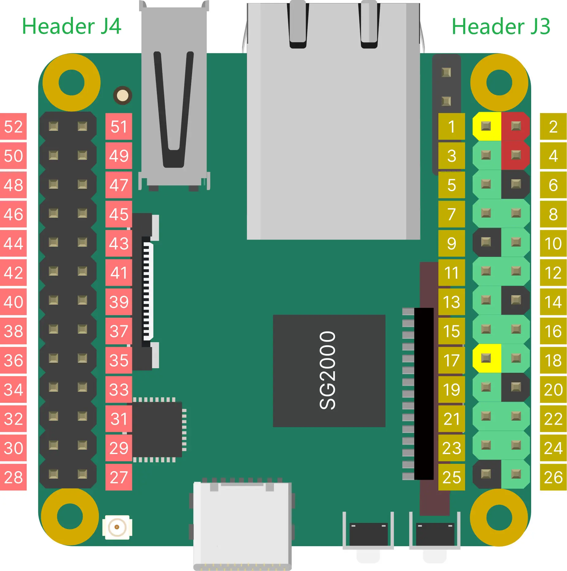
Header J3
GPIO on Header J3 use 3.3V logic levels.
| wiringX | PIN NAME | PIN# | PIN# | PIN NAME | wiringX |
|---|---|---|---|---|---|
| 3V3 | 1 | 2 | VSYS(5V) | ||
| 3 | B20 | 3 | 4 | VSYS(5V) | |
| 5 | B21 | 5 | 6 | GND | |
| 7 | B18 | 7 | 8 | A16 | 8 |
| GND* | 9 | 10 | A17 | 10 | |
| 11 | B11 | 11 | 12 | B19 | 12 |
| 13 | B12 | 13 | 14 | GND | |
| 15 | B22 | 15 | 16 | A20 | 16 |
| 3V3 | 17 | 18 | A19 | 18 | |
| 19 | B13 | 19 | 20 | GND | |
| 21 | B14 | 21 | 22 | A18 | 22 |
| 23 | B15 | 23 | 24 | B16 | 24 |
| GND | 25 | 26 | A28 | 26 |
GND*: Pin 9 is a low-level GPIO in the V1.1 version of the hardware, and is GND in the V1.2 version and later.
Header J4
GPIO on Header J4 use 1.8V logic levels.
Most of the pins on this header have dedicated functions, such as MIPI DSI signals, Touch Screen signals, and audio signals. If there is no special requirement, it is not recommended to use the pins on this header as GPIO.
| wiringX | PIN NAME | PIN# | PIN# | PIN NAME | wiringX |
|---|---|---|---|---|---|
| VSYS(5V) | 52 | 51 | AUDIO_OUT_R | ||
| 50 | B1 | 50 | 49 | AUDIO_OUT_L | |
| 48 | B2 | 48 | 47 | AUDIO_IN_R | |
| 46 | B3 | 46 | 45 | AUDIO_IN_L | |
| 44 | E2 | 44 | 43 | 3V3 | |
| 42 | E1 | 42 | 41 | C18 | 41 |
| 40 | E0 | 40 | 39 | C19 | 39 |
| GND | 38 | 37 | GND | ||
| 36 | C20 | 36 | 35 | C16 | 35 |
| 34 | C21 | 34 | 33 | C17 | 33 |
| GND | 32 | 31 | GND | ||
| 30 | C14 | 30 | 29 | C12 | 29 |
| 28 | C15 | 28 | 27 | C13 | 27 |
Development Environment Setup
Build environment on Ubuntu22.04
You can also use Ubuntu installed in a virtual machine, Ubuntu installed via WSL on Windows, or Ubuntu-based systems using Docker.
-
Install the tools that compile dependencies
sudo apt-get install wget git make -
Get example source code
git clone https://github.com/milkv-duo/duo-examples.git -
Prepare compilation environment
cd duo-examples
source envsetup.sh
The first time you source it, the required compilation toolchain will be automatically downloaded. The downloaded directory is named
host-tools. The next time the compilation environment is loaded, the directory will be detected. If it already exists, it will not be downloaded again.In the source process, you need to enter the required compilation target as prompted:
Select Product:
1. Duo (CV1800B)
2. Duo256M (SG2002) or DuoS (SG2000)
If the target board is Duo, select
1, if the target board is Duo256M or DuoS, select2. Since Duo256M and DuoS support both RISCV and ARM architectures, you need to continue to select as prompted:Select Arch:
1. ARM64
2. RISCV64
Which would you like:If the test program needs to be run on a ARM system, select
1, if it is an RISCV system, select2.In the same terminal, you only need to source it once.
-
Compile testing
Take hello-world as an example, enter the hello-world directory and execute make:
cd hello-world
make
After the compilation is successful, send the generated
helloworldexecutable program to the Duo device through the network port or the USB network. For example, the USB-NCM method supported by the default firmware, Duo’s IP is 192.168.42.1, the user name isroot, and the password ismilkv.scp -O helloworld [email protected]:/root/After sending successfully, run
./helloworldin the terminal logged in via ssh or serial port, and it will printHello, World![root@milkv]~# ./helloworld
Hello, World!At this point, our compilation and development environment is ready for use.
How to create your own project
You can simply copy existing examples and make necessary modifications. For instance, if you need to manipulate a GPIO, you can refer to the blink example. LED blinking is achieved by controlling the GPIO's voltage level. The current SDK utilizes the WiringX library for GPIO operations, which has been adapted specifically for Duo. You can find the platform initialization and GPIO control methods in the blink.c code for reference.
- Create your own project directory called
my-project. - Copy the
blink.candMakefilefiles from theblinkexample to themy-projectdirectory. - Rename
blink.cto your desired name, such asgpio_test.c. - Modify the
Makefileby changingTARGET=blinktoTARGET=gpio_test. - Modify
gpio_test.cto implement your own code logic. - Execute the
makecommand to compile. - Send the generated
gpio_testexecutable program to Duo for execution.
Note:
- Creating a new project directory is not mandatory to be placed within the
duo-examplesdirectory. You can choose any location based on your preference. Before executing themakecompilation command, it is sufficient to load the compilation environment from theduo-examplesdirectory (source /PATH/TO/duo-examples/envsetup.sh). - Within the terminal where the compilation environment (envsetup.sh) is loaded, avoid compiling Makefile projects for other platforms such as ARM or X86. If you need to compile projects for other platforms, open a new terminal.
Code example
GPIO Usage Example
Here is an example of working with GPIO. It will toggle pin 20 on Duo every 1 second, pulling it high and then low. The physical pin number for pin 20 is 15 in the WiringX numbering system.
#include <stdio.h>
#include <unistd.h>

#include <wiringx.h>

int main() {
    int DUO_GPIO = 15;

    // Duo:     milkv_duo
    // Duo256M: milkv_duo256m
    // DuoS:    milkv_duos
    if(wiringXSetup("milkv_duo", NULL) == -1) {
        wiringXGC();
        return -1;
    }

    if(wiringXValidGPIO(DUO_GPIO) != 0) {
        printf("Invalid GPIO %d\n", DUO_GPIO);
    }

    pinMode(DUO_GPIO, PINMODE_OUTPUT);

    while(1) {
        printf("Duo GPIO (wiringX) %d: High\n", DUO_GPIO);
        digitalWrite(DUO_GPIO, HIGH);
        sleep(1);
        printf("Duo GPIO (wiringX) %d: Low\n", DUO_GPIO);
        digitalWrite(DUO_GPIO, LOW);
        sleep(1);
    }

    return 0;
}
After compiling and running it on Duo, you can use a multimeter or an oscilloscope to measure the state of pin 20 and verify if it matches the expected behavior.
You can also use the onboard LED pin to verify the behavior. By observing the on/off state of the LED, you can intuitively determine if the program is executing correctly. The WiringX pin number for the LED is 25. Simply modify the code mentioned above by replacing pin 15 with pin 25. However, please note that the default firmware has a script to control LED blinking on startup, which needs to be disabled. You can refer to the example explanation for blink below for instructions on how to disable it.
I2C Usage Example
Here is an example of I2C communication:
#include <stdio.h>
#include <unistd.h>
#include <stdint.h>

#include <wiringx.h>

#define I2C_DEV "/dev/i2c-1"

#define I2C_ADDR 0x04

int main(void)
{
    int fd_i2c;
    int data = 0;

    // Duo:     milkv_duo
    // Duo256M: milkv_duo256m
    // DuoS:    milkv_duos
    if(wiringXSetup("milkv_duo", NULL) == -1) {
        wiringXGC();
        return -1;
    }

    if ((fd_i2c = wiringXI2CSetup(I2C_DEV, I2C_ADDR)) <0) {
        printf("I2C Setup failed: %d\n", fd_i2c);
        wiringXGC();
        return -1;
    }

    // TODO
}
SPI Usage Example
Here is an example of SPI communication:
#include <stdio.h>
#include <unistd.h>
#include <stdint.h>

#include <wiringx.h>

int main(void)
{
    int fd_spi;

    // Duo:     milkv_duo
    // Duo256M: milkv_duo256m
    // DuoS:    milkv_duos
    if(wiringXSetup("milkv_duo", NULL) == -1) {
        wiringXGC();
        return -1;
    }

    if ((fd_spi = wiringXSPISetup(0, 500000)) <0) {
        printf("SPI Setup failed: %d\n", fd_spi);
        wiringXGC();
        return -1;
    }

    // TODO
}
UART Usage Example
Here is an example of UART communication using UART4 on pins 4/5:
#include <stdio.h>
#include <unistd.h>

#include <wiringx.h>

int main() {
    struct wiringXSerial_t wiringXSerial = {115200, 8, 'n', 1, 'n'};
    char buf[1024];
    int str_len = 0;
    int i;
    int fd;

    // Duo:     milkv_duo
    // Duo256M: milkv_duo256m
    // DuoS:    milkv_duos
    if(wiringXSetup("milkv_duo", NULL) == -1) {
        wiringXGC();
        return -1;
    }

    if ((fd = wiringXSerialOpen("/dev/ttyS4", wiringXSerial)) < 0) {
        printf("Open serial device failed: %d\n", fd);
        wiringXGC();
        return -1;
    }

    wiringXSerialPuts(fd, "Duo Serial Test\n");

    while(1)
    {
        str_len = wiringXSerialDataAvail(fd);
        if (str_len > 0) {
            i = 0;
            while (str_len--)
            {
                buf[i++] = wiringXSerialGetChar(fd);
            }
            printf("Duo UART receive: %s\n", buf);
        }
    }

    wiringXSerialClose(fd);

    return 0;
}
Testing Method:
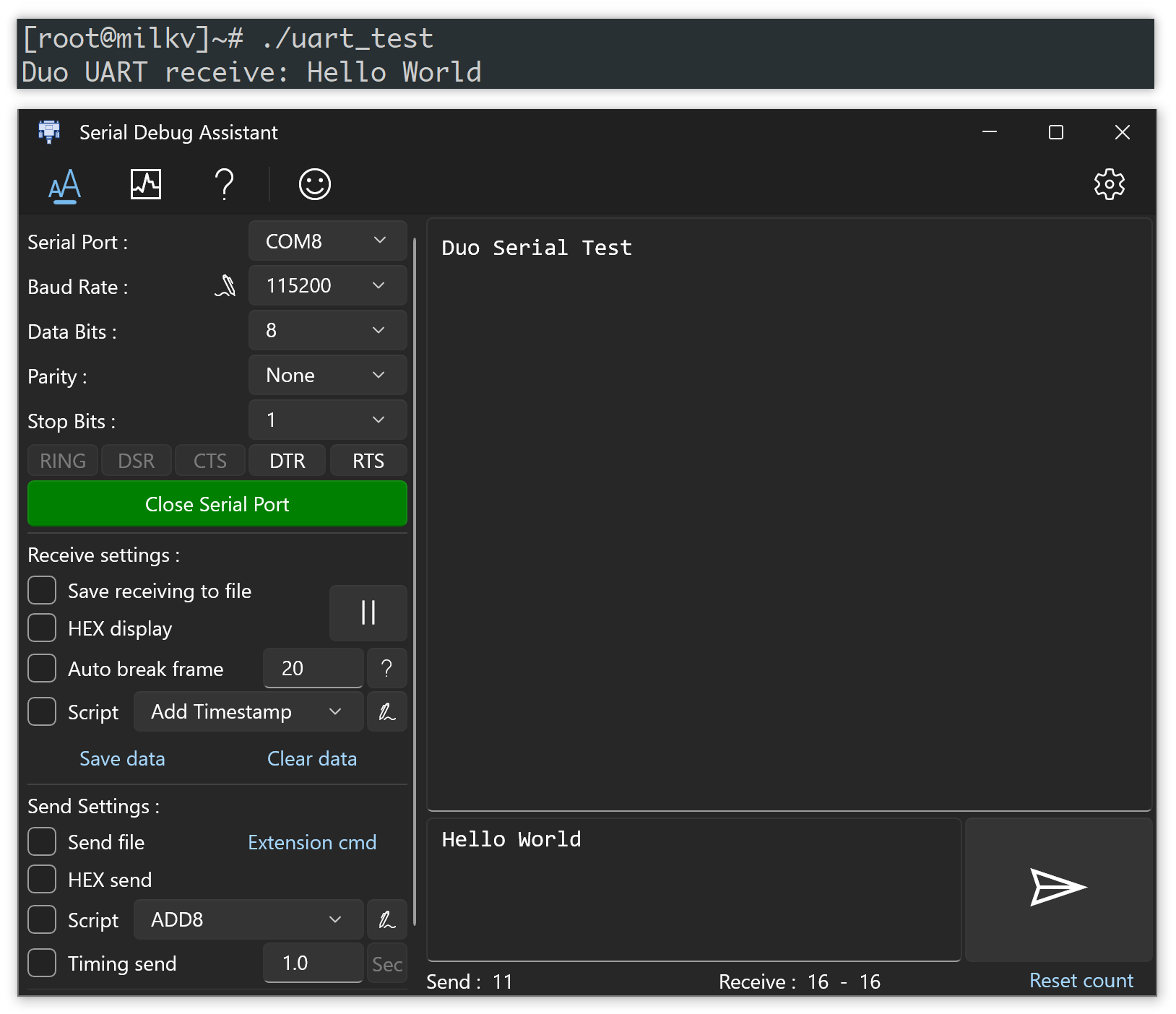
The RX of the USB to serial converter cable is connected to pin 4 (UART4_TX) of Duo, the TX of the serial cable is connected to pin 5 (UART4_RX) of Duo, and the GND of the serial cable is connected to the GND of Duo. On the computer, configure the COM port and parameters using a serial debugging tool.
The compiled executable of the above program is named uart_test. After uploading it to Duo via SSH and running it, you should be able to see the string Duo Serial Test received in the serial tool on your computer. If you send the string Hello World from the serial tool, you will also see the corresponding string received on the Duo's terminal. This confirms that the serial communication is functioning correctly.
Explanation of each example
hello-world
Source code: https://github.com/milkv-duo/duo-examples/tree/main/hello-world
A simple example that doesn't interact with Duo peripherals, only prints the output "Hello, World!" to verify the development environment.
blink
Source code: https://github.com/milkv-duo/duo-examples/tree/main/blink
This example demonstrates how to control an LED connected to a GPIO pin. It uses the WiringX library to toggle the GPIO pin's voltage level, resulting in the LED blinking.
The blink.c code includes platform initialization and GPIO manipulation methods from the WiringX library.
To test the blink example, which involves LED blinking, you need to disable the script responsible for the automatic LED blinking on the default firmware of Duo. In the Duo terminal, execute the following command:
mv /mnt/system/blink.sh /mnt/system/blink.sh_backup && sync
This command renames the LED blinking script. After restarting Duo, the LED will no longer blink.
Once you have finished testing the blink program implemented in C, if you want to restore the LED blinking script, you can rename it back using the following command and then restart Duo:
mv /mnt/system/blink.sh_backup /mnt/system/blink.sh && sync
PWM
Source code:https://github.com/milkv-duo/duo-examples/tree/main/pwm
Set the PWM signal on a pin by manually entering the pin number and duty cycle. After running the program, please follow the prompts to enter the [pin number]:[duty] cycle to set the PWM signal on the corresponding pin, such as 3:500.
ADC
adcRead reads the voltage value
Source code: https://github.com/milkv-duo/duo-examples/tree/main/adc
Reading the measured value of the ADC is divided into two versions: shell script and C language. After starting, select the ADC to be read according to the output prompts. After selection, the voltage value measured by the ADC will be printed in a loop.
I2C
I2C source code directory: https://github.com/milkv-duo/duo-examples/tree/main/i2c
BMP280 Temperature Barometer Sensor
Source code: https://github.com/milkv-duo/duo-examples/tree/main/i2c/bmp280_i2c
This example code shows how to interface the Milk-V Duo with the popular BMP280 temperature and air pressure sensor manufactured by Bosch.
VL53l0X Time of Flight distance sensor
Source code: https://github.com/milkv-duo/duo-examples/tree/main/i2c/vl53l0x_i2c
Use the TOF distance sensor VL53L0X module via the I2C interface to read the measured distance.
SSD1306 OLEDs
Source code: https://github.com/milkv-duo/duo-examples/tree/main/i2c/ssd1306_i2c
Display strings on SSD1306 OLED display via I2C interface.
ADXL345 Three-axis acceleration sensor
Source code: https://github.com/milkv-duo/duo-examples/blob/main/i2c/adxl345_i2c
Read the acceleration data obtained by ADXL345 through the I2C interface, read it every 1 second, and print the result on the screen.
LCM1602 Display Moudle
Source code: https://github.com/milkv-duo/duo-examples/blob/main/i2c/lcm1602_i2c
Display strings on the 1602 LCD screen via the I2C interface.
LCM2004 Display Moudle
Source code: https://github.com/milkv-duo/duo-examples/blob/main/i2c/lcm2004_i2c
Display string on 2004 LCD screen via I2C interface.
TCS34725 Color sensor
Source code: https://github.com/milkv-duo/duo-examples/blob/main/i2c/tcs34725_i2c
Read the TCS34725 color sensor through the I2C interface and output the obtained data.
SPI
SPI source code directory: https://github.com/milkv-duo/duo-examples/tree/main/spi
MAX6675 Temperature Sensor
Source code: https://github.com/milkv-duo/duo-examples/tree/main/spi/max6675_spi
Connect the K-type thermocouple measurement module MAX6675 through the SPI interface to measure the current temperature on the sensor.
RC522 Radio Frequency Identification Module
Source code: https://github.com/milkv-duo/duo-examples/tree/main/spi/rc522_spi
Connect the RC522 RFID read-write module via the SPI interface to read the card ID and type and output them to the screen.
Compile wiringX library
Duo firmware already contains the compiled wiringX library (/usr/lib/libwiringx.so) and can be used directly. If you need to compile the source code of wiringX to generate the library, you can compile it as follows.
We compile it on an Ubuntu host or other Linux distribution.
*Note: Part of Duo's wiringX code has not yet been integrated into the upstream wiringX repo. In actual use, please give priority to using the wiringX library in Duo firmware.
Download wiringX source code
git clone https://github.com/wiringX/wiringX.git
Modify CMakeLists.txt
Enter the code directory:
cd wiringX
The wiringX project is compiled using cmake. You need to modify CMakeLists.txt through vi or other editors to add the cross-compilation toolchain and compilation parameters:
diff --git a/CMakeLists.txt b/CMakeLists.txt
index 8909393..6918181 100644
--- a/CMakeLists.txt
+++ b/CMakeLists.txt
@@ -17,6 +17,11 @@ set(CMAKE_EXE_LINKER_FLAGS " -Wl,-rpath=/usr/local/lib/,-rpath=/usr/lib/,-rpath=
 set(CMAKE_SHARED_LINKER_FLAGS " -Wl,-rpath=/usr/local/lib/,-rpath=/usr/lib/,-rpath=/lib/")
 set(CMAKE_MODULE_LINKER_FLAGS " -Wl,-rpath=/usr/local/lib/,-rpath=/usr/lib/,-rpath=/lib/")

+set(CMAKE_C_COMPILER "${CMAKE_CURRENT_SOURCE_DIR}/host-tools/gcc/riscv64-linux-musl-x86_64/bin/riscv64-unknown-linux-musl-gcc")
+set(CMAKE_CXX_COMPILER "${CMAKE_CURRENT_SOURCE_DIR}/host-tools/gcc/riscv64-linux-musl-x86_64/bin/riscv64-unknown-linux-musl-g++")
+set(CMAKE_C_FLAGS "${CMAKE_C_FLAGS} -mcpu=c906fdv -march=rv64imafdcv0p7xthead -mcmodel=medany -mabi=lp64d")
+set(CMAKE_EXE_LINKER_FLAGS "${CMAKE_EXE_LINKER_FLAGS} -D_LARGEFILE_SOURCE -D_LARGEFILE64_SOURCE -D_FILE_OFFSET_BITS=64")
+
 # Start uninstaller generator
 function(WRITE_UNINSTALL_TARGET_SCRIPT)
     # Create uninstall target template file, if it doesn't exist...
There are two variables that need to be noted and configured according to your own file path:
- CMAKE_C_COMPILER: The path to gcc in the cross-compilation toolchain
- CMAKE_CXX_COMPILER: path to g++ in the cross-compilation toolchain
Download link for cross-compilation toolchain: host-tools.tar.gz. You can download and unzip it through the wget command:
wget https://sophon-file.sophon.cn/sophon-prod-s3/drive/23/03/07/16/host-tools.tar.gz
tar -xf host-tools.tar.gz
If you have ever compiled duo-buildroot-sdk, the host-tools directory in its root directory is the directory of the cross toolchain. There is no need to re-download, you can directly modify the CMAKE_CURRENT_SOURCE_DIR field to specify the directory. Or create a soft link pointing to the directory.
Modify code
Since the time-related definitions in the cross toolchain are slightly different from those in wiringX, add the following two lines of modification:
diff --git a/src/wiringx.c b/src/wiringx.c
index 034674a..4171a75 100644
--- a/src/wiringx.c
+++ b/src/wiringx.c
@@ -113,6 +113,9 @@ static struct spi_t spi[2] = {
        } while(0)
 #endif

+typedef time_t __time_t;
+typedef suseconds_t __suseconds_t;
+
 /* Both the delayMicroseconds and the delayMicrosecondsHard
    are taken from wiringPi */
 static void delayMicrosecondsHard(unsigned int howLong) {
Compile
Compiling in cmake will create some intermediate directories and files, so we create a new build directory and enter this directory to complete the compilation:
mkdir build
cd build
cmake ..
make
After compilation is completed, the libwiringx.so generated in the current build directory is the wiringX library we need.
Points to Consider
If you encounter compilation errors, you can try to change the version of cmake. For example, you can manually install the latest 3.27.6 version:
wget https://github.com/Kitware/CMake/releases/download/v3.27.6/cmake-3.27.6-linux-x86_64.sh
chmod +x cmake-3.27.6-linux-x86_64.sh
sudo sh cmake-3.27.6-linux-x86_64.sh --skip-license --prefix=/usr/local/
The manually installed cmake is in /usr/local/bin. At this time, use the cmake --version command to check its version number, which should be:
cmake version 3.27.6
wiringX APIs
General
int wiringXSetup(char *name, ...)
To initialize the WiringX library for configuring and managing GPIO pins:
- Duo
wiringXSetup("milkv_duo", NULL) - Duo256M
wiringXSetup("milkv_duo256m", NULL) - DuoS
wiringXSetup("milkv_duos", NULL)
int wiringXValidGPIO(int pin)
To check if a GPIO pin is available.
void delayMicroseconds(unsigned int ms)
Delay for how many milliseconds.
int wiringXGC(void)
To release resources.
char *wiringXPlatform(void)
Return platform information.
GPIO
int pinMode(int pin, pinmode_t mode)
Set the working mode for the specified pin, where pin is the pin number, and mode can be:
- PINMODE_INPUT input mode
- PINMODE_OUTPUT output mode
- PINMODE_INTERRUPT interrupt mode
int digitalRead(int pin)
Read the input value of the specified pin, and the return value is HIGH or LOW.
int digitalWrite(int pin, enum digital_value_t value)
Set the output value for the specified pin, where value can be:
- HIGH high level
- LOW low level
int waitForInterrupt(int pin, int ms)
Wait for an interrupt to occur on pin, with a timeout of ms milliseconds. This function has been deprecated. It is recommended to use wiringXISR
int wiringXISR(int pin, enum isr_mode_t mode)
Configure pin as an interrupt mode, with several modes for mode:
- ISR_MODE_RISING
- ISR_MODE_FALLING
- ISR_MODE_BOTH
I2C
int wiringXI2CSetup(const char *dev, int addr)
Configure the I2C node and I2C address.
int wiringXI2CRead(int fd)
Read 1 byte of data.
int wiringXI2CReadReg8(int fd, int reg)
Read 1 byte of data from the reg register.
int wiringXI2CReadReg16(int fd, int reg)
Read 2 bytes of data from the reg register.
int wiringXI2CWrite(int fd, int reg)
Write the address of the register reg.
int wiringXI2CWriteReg8(int fd, int reg, int value8)
Write the 8-bit data value8 to the register reg.
int wiringXI2CWriteReg16(int fd, int reg, int value16)
Write the 16-bit data value16 to the register reg.
SPI
int wiringXSPISetup(int channel, int speed)
Configure the channel (0 on Duo) and speed (default to 500000) of the SPI device.
int wiringXSPIDataRW(int channel, unsigned char *data, int len)
The SPI bus writes data on the rising edge and reads data on the falling edge. Therefore, this function performs both read and write operations simultaneously, resulting in the read data overwriting the written data. Please be cautious when using it.
int wiringXSPIGetFd(int channel)
Get the file descriptor of the SPI device, with the channel defaulting to 0 on Duo.
UART
int wiringXSerialOpen(const char *dev, struct wiringXSerial_t serial)
Open the serial port device, where dev is the device descriptor and serial is a structure that needs to be filled with serial port-related parameters. For more details, please refer to the UART Usage Example.
typedef struct wiringXSerial_t {
    unsigned int baud;           // baudrate
    unsigned int databits;       // 7/8
    unsigned int parity;         // o/e/n
    unsigned int stopbits;       // 1/2
    unsigned int flowcontrol;    // x/n
} wiringXSerial_t;
void wiringXSerialClose(int fd)
Close the serial port.
void wiringXSerialFlush(int fd)
Flush the buffer.
void wiringXSerialPutChar(int fd, unsigned char c)
Output a character.
void wiringXSerialPuts(int fd, const char *s)
Output a string.
void wiringXSerialPrintf(int fd, const char *message, ...)
Format output.
int wiringXSerialDataAvail(int fd)
Return the number of data received in the buffer.
int wiringXSerialGetChar(int fd)
Read a character from the serial port device.
PWM
wiringXPWMSetPeriod(int pin, long period)
Set the period of the PWM pin, pin is the PWM pin number, period is in nanoseconds.
int wiringXPWMSetDuty(int pin, long duty_cycle)
Set the high level time of the PWM pin in one cycle, duty_cycle is in nanoseconds.
int wiringXPWMSetPolarity(int pin, int polarity)
Set the PWM pin polarity, the polarity is 0 or 1:
- 0 normal
- 1 inversed
int wiringXPWMEnable(int pin, int enable)
Enable or disable PWM pin output, enable is 0 or 1:
- 0: disable
- 1: enable