8051 Core
Introduction
The CPU used by Duo contains an 8051 core. The 8051 subsystem is located in a module that is independently powered by the RTC. The subsystem is configured with an 8051, an I2C/UART/SPI NOR/SD controller, a Timer/WDT, interrupt management, and a Mailbox IP. The system software can use the 8051 to manage wake-up conditions and wake up the system while it is in sleep mode, and communicate with external devices through peripheral controllers.
Quick Start
8051 core compilation guide
Source Code: github.
run:
git clone https://github.com/milkv-duo/duo-8051.git
cd duo-8051/sdcc/mars/project/base_project
make clean && make
After successful compilation, the compiled firmware mars_mcu_fw.bin can be found in sdcc/mars/project/base_project/output.
How to load firmware
First download the firmware and tools and unzip the zip package:firmware.zip.
Ⅰ. Load firmware in 8051-SRAM:
-
Copy
8051_up,mars_mcu_fw.bin, andblink.shinto/mnt/data, and grant execution and read permissions. -
Execute
8051_upto automatically update the firmware and start the 8051 core. -
Execute
blink.sh. This script will send data to the 8051 core and cause the blue LED to flash (please confirm that /mnt/system/blink.sh has been removed before executing this script).
The 8051 kernel firmware cannot exceed 8KB when running this method. Exceeding the limit may cause it to not run.
Ⅱ.Load firmware in DDR memory:
- Change the memory allocation in the SDK and modify
build/boards/[chip model]/[board config]/memmap.py.
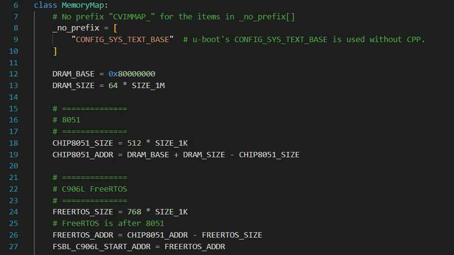
Add the following content in MemoryMap:
# ==============
# 8051
# ==============
CHIP8051_SIZE = 512 * SIZE_1K
CHIP8051_ADDR = DRAM_BASE + DRAM_SIZE - CHIP8051_SIZE
Modify the following content:
# ==============
# C906L FreeRTOS
# ==============
FREERTOS_SIZE = 768 * SIZE_1K
# FreeRTOS is after 8051
FREERTOS_ADDR = CHIP8051_ADDR - FREERTOS_SIZE
FSBL_C906L_START_ADDR = FREERTOS_ADDR
-
Recompile the firmware and burn it to the Duo board.
-
Copy
8051_up,mars_mcu_fw.bin,blink.sh, and8051_boot_cfg.iniinto/mnt/data, and grant execution and read permissions. -
Execute
8051_upto automatically update the firmware and start the 8051 core. -
Execute
blink.sh. This script will send information to the 8051 core and cause the blue LED to flash (please confirm that /mnt/system/blink.sh has been removed before executing this script).
If you want to customize the DDR memory size of 8051 to store firmware, please modify:
CHIP8051_SIZE = 512 * SIZE_1K
in which 512 is the custom size, and modify the address in 8051_boot_cfg.ini to be the custom address.
The Duo address calculation formula is "2147483648+ 64*1048576-[custom size]*1024".
The Duo-256M address calculation formula is "2147483648+256*1048576-[custom size]*1024".
(note that when filling the address to config file, it must be converted into a hexadecimal address 0xXXXXXXX.)
8051 SDCC
Introduction
SDCC is a cross-compiler whose target CPU is 8051. It is used in Duo to compile 8051 core related code.
8051 on-chip resources
Peripheral resources
8051 comes with peripherals
-
Three 16bit Timers.
-
One uart, multiplexed
PWR_UART_RX/PWR_UART_TX.
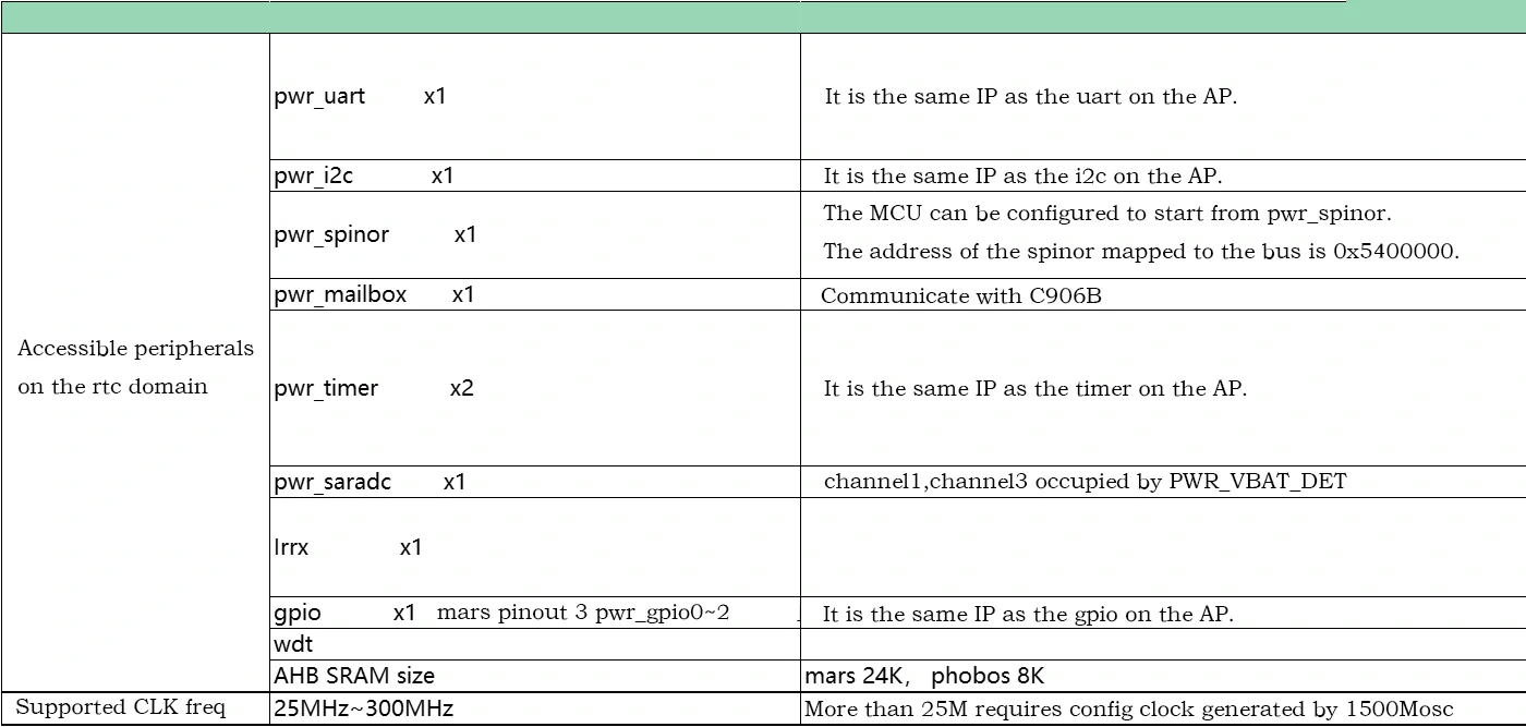
rtc domain peripherals
8051 is generally used in low-power scenarios. The rtc domain will not lose power during poweroff/suspend, which is a no die domain. Therefore, the peripherals used by 8051 in most cases are on the rtc domain. The peripheral table of rtc domain is as follows:
AP on-chip peripherals
8051 can access 0x0 ~ 0xFFFFFFFF when the AP is powered on. In theory, all peripherals on the AP side can be accessed. However, whether the interrupt signal of the corresponding peripheral device can be transmitted to 8051, you need to check the aptortc interrupt table.
interrupt controller
Hardware structure
The interrupt control of 8051 is divided into three parts:
-
8051 on-chip interrupt.
-
Peripheral interrupt signal on rtc.
-
The AP side interrupt.
The interrupt numbers and supported interrupt types defined by 8051 are used as shown in the following table:
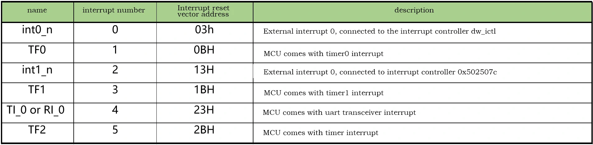
The peripheral interrupt signal on the rtc can be packaged and connected to the 8051 through external interrupt 0 and external interrupt 1, which can be understood as sharing the int0_n and int1_n interrupt lines. As shown in the figure below, irq_ap2rtc[1:0] handles interrupt events on the AP.
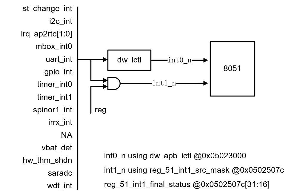
The interrupt event on the AP side is ORed through 0x3000250 and 0x3000254, and the interrupt on the AP side is packaged and transmitted to irq_ap2rtc[0]. The interrupt event on the AP side is packaged and transmitted to irq_ap2rtc[1] through 0x3000260 and 0x3000264.
Please refer to "reg_top_misc.xlsx" for AP side interrupt event enable and view status. For supported interrupt types and corresponding ap interrupt number, please refer to sheet "toptortc" in "cv180x_interrupt.xlsx".
Interrupt the configuration process
-
Configure interrupt events and enable corresponding interrupts.
-
0x3000248 = 0x01enables rtc2ap bus conversion. -
Check the bit corresponding to the interrupt number enable
rtcsys_ap2rtc_irq0_sigen0/rtcsys_ap2rtc_irq0_sigen1orrtcsys_ap2rtc_irq1_sigen0/rtcsys_ap2rtc_irq1_sigen1. -
enable
irq_ap2rtc[0]or enableirq_ap2rtc[1]. -
enable
int0_nor enableint1_n. -
After the interrupt response enters the external interrupt processing function, check dw_ictl or reg
0x502507cstatus to see if it is due to theirq_ap2rtc[0]orirq_ap2rtc[1]event response. If so, checkrtcsys_ap2rtc_irq0_status0/crtcsys_ap2rtc_irq0_status1orrtcsys_ap2rtc_irq1_status0/rtcsys_ap2rtc_irq1_status1View the responding AP interrupt event which one.
Interrupt control example:
#if TEST_APTORTC_ICTL

static int __xdata aptortc_count = 0;
int test_aptortc_gpioa_isr(char irqn, int *priv)
{
    write_robot(0x0302004c, 0x8000);
    printf("gpio0 interrupt\n");
    aptortc_count++;
}

void test_aptortc_irq()
{
    printf("test aptortc irq\n");
    write_robot(0x03020004, 0x100c0020);    //Set gpioA gpio15 as output
    write_robot(0x03001908, 0x44);          //Switch pinmux to pull-up
    write_robot(0x03020030, 0xa000);        //Enable interrupts
    write_robot(0x03020038, 0x8000);        //Set up edge triggering

    ap2rtc_irq_init();
    ap2rtc_request_irq(17, test_aptortc_gpioa_isr, NULL);

    ap2rtc_irq_unmask(17);
    dw_ictl_unmask(IRQ_AP2RTC0_INTR);
    irq_enable();

    printf("REG_51_INT1_SRC_MASK: 0x%081x\n", read_robot(REG_51_INT1_SRC_MASK));
    EX0 = 1;
    EX1 = 1;
    EA = 1;
    while(aptortc_count == 0)
        printf("gpioA irq 0x3020040 = %x, aptortc_irq status = %x\n",read_robot(0x3020040),read_robot(0x3000258));

    printf("aptortc_count = %d\n",aptortc_count);
    irq_disable();
}
#endif
8051 address mapping and startup method
The 8051 core address space is divided into the following three parts:
-
Program memory:Internal rom(64K)+External rom(64K~4M by code banking). -
Data memory:Internal ram(256byte)+External ram(64K~4G). -
Special register(128byte).
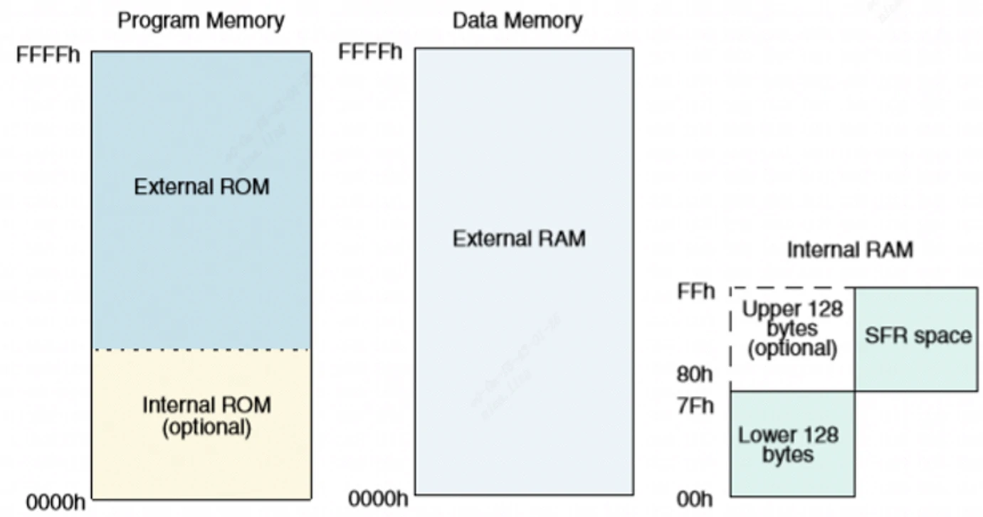
8051 itself does not come with externel rom and externel ram. What is expressed here is the bus addressability. In the system, externel rom and externel rom are mapped to the memory on the chip through 0x5025020 and 0x5025024 or sfr (0xfd, 0xfc), such as AHB SRAM, TPU SRAM, DDR, SPINOR address space.
8051 module responsible for address mapping
-
u_mcu_8051_iram. -
u_mcu_8051_sfr_wp(Responsible for the conversion of SFR to AHB bus). -
u_mcu_8051_xdata_wp(Responsible for mapping externel rom and externel ram).
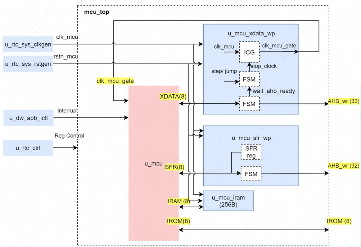
The conversion from SFR to AHB bus is mainly used to read and write registers. In the code, robot_read and robot_write are through this interface.
The 8051 address line has a bit width of 16 bits and the data line has a bit width of 8 bits. The XDATA interface maps externel rom and externel ram to 32-bit address space such as AHB SRAM, TPU SRAM, DDR and SPINOR.
Notes on address mapping and startup methods
-
cv181x and cv180x need to configure
reg_51_rom_addr_def = 1in0x5025020. -
8051 irom can only be mapped to AHB SRAM by default. You can modify
reg_51irom_ioffset[4:0]in0x5025024to configure the offset of the first address on AHB SRAM.The first address is0x5200000 + reg_51irom_ioffset[4:0] * 2KB. Only whenreg_51_mem_ea_n = 1(the configured externel rom does not exist), the mcu will start from the irom. If the irom address is exceeded, it will go to the externel rom to fetch address.Whenreg_51_mem_ea_n = 0, it starts from externel rom and does not use irom. -
The first address of externel rom can be mapped to AHB SRAM, TPU SRAM, DDR and SPINOR address space. The
reg_51xdata_ioffset0[20:0]of0x5025020can be configured to determine the mapping address. The first address of externel rom isreg_51xdata_ioffset0[20:0] * 2KB. -
The first address of Externel ram can be mapped to AHB SRAM, TPU SRAM, DDR, and can be configured with
reg_51xdata_doffset0[20:0]orSFR(0xfd, 0xfc). -
If
reg_51xdata_doffset0[20:0]is configured, the first address of the external ram isreg_51xdata_doffset0[20:0] * 2KB. At this time, sfr0xfc = 0,0xfd = 0must be set, and the address ofreg_51xdata_doffset0[20:0]andSFRmust be configured at the same time. It is the superimposed effect of the two. -
When
reg_51xdata_doffset0[20:0] = 0, configureSFR{0xfd,0xfc}, then the first address of externel ram isSFR{0xfd,0xfc} * 64KB.
Since most 8051 are used in low-power consumption scenarios, most of the startup methods are that both program memory and data memory are mapped to AHB SRAM.
Modify the division of external rom and external ram
Modify the MakeFile in the SDCC code directory sdcc/mars/project/base_project:
# ------------------------------------------------------
# Memory Layout

# PRG Size = 4K Bytes
CODE_SIZE = --code-loc 0x0000 --code-size 0x1F00

# INT-MEM Size = 256 Bytes
#IRAM_SIZE = --idata-loc 0x0000  --iram-size 256

# EXT-MEM Size = 32K Bytes
XRAM_SIZE = --xram-loc 0x1900 --xram-size 0x400

# ------------------------------------------------------
# MCS51 Options
Modify CODE_SIZE, XRAM_SIZE to change the size of external rom and external ram.
AHB SRAM register size is 8KB. When using AHB SRAM as external rom, be careful not to allocate more than 8KB memory.
SFR register
The SFR (Special Function Register) is located at 80H~FFH. SFR registers are divided into two categories, one is the SFR register that comes with the 8051, and the other is the extended SFR register. The complete SFR register can be found at d8051_db.pdf 。
For more information on 8051 basic knowledge, please refer to the website link and datasheet d8051_db.pdf 。
Implementation of robot_write and robot_read
The following figure shows the relevant SFR registers that implement robot_write and robot_read :
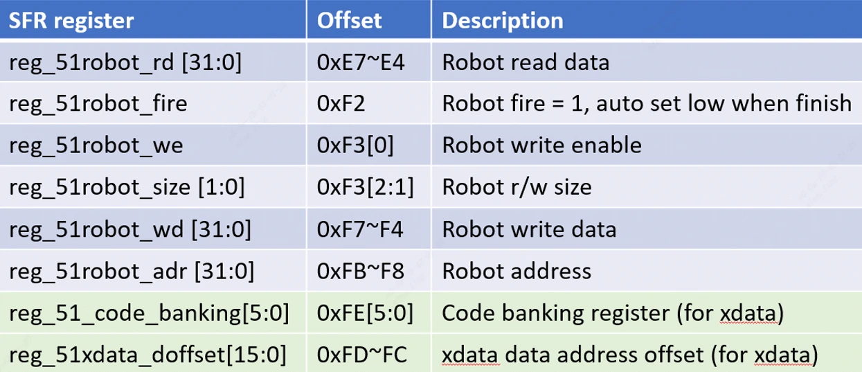
robot_write :
-
Set
reg_51robot_size、reg_51robot_adr、reg_51robot_wd、reg_51robot_we = 1。 -
reg_51robot_fireis set to 1 during writing, please poll this register untilreg_51robot_fire == 0.
robot_read :
-
Set
reg_51robot_size、reg_51robot_adr、reg_51robot_we = 0。 -
reg_51robot_fireis set to 1 during reading, please poll this register untilreg_51robot_fire == 0. -
Read data from
reg_51robot_rd.
Firmware loading tool 8051_UP
This tool is used to load the bin firmware into memory and start the 8051 core.
Source Code: github。
Compilation method
run:
git clone https://github.com/milkv-duo/duo-examples.git
git clone https://github.com/milkv-duo/duo-8051.git
cp -r ./duo-8051/tools/8051_up ./duo-examples
cd ./duo-examples/8051_up
source ../envsetup.sh
make
After successful compilation, the executable file 8051_up will be generated in the duo-examples/8051_up directory.
The compiled software can be found in firmware.zip . For the compilation method, please refer to the Demo in duo-examples .