Sensor Demo
DHT22
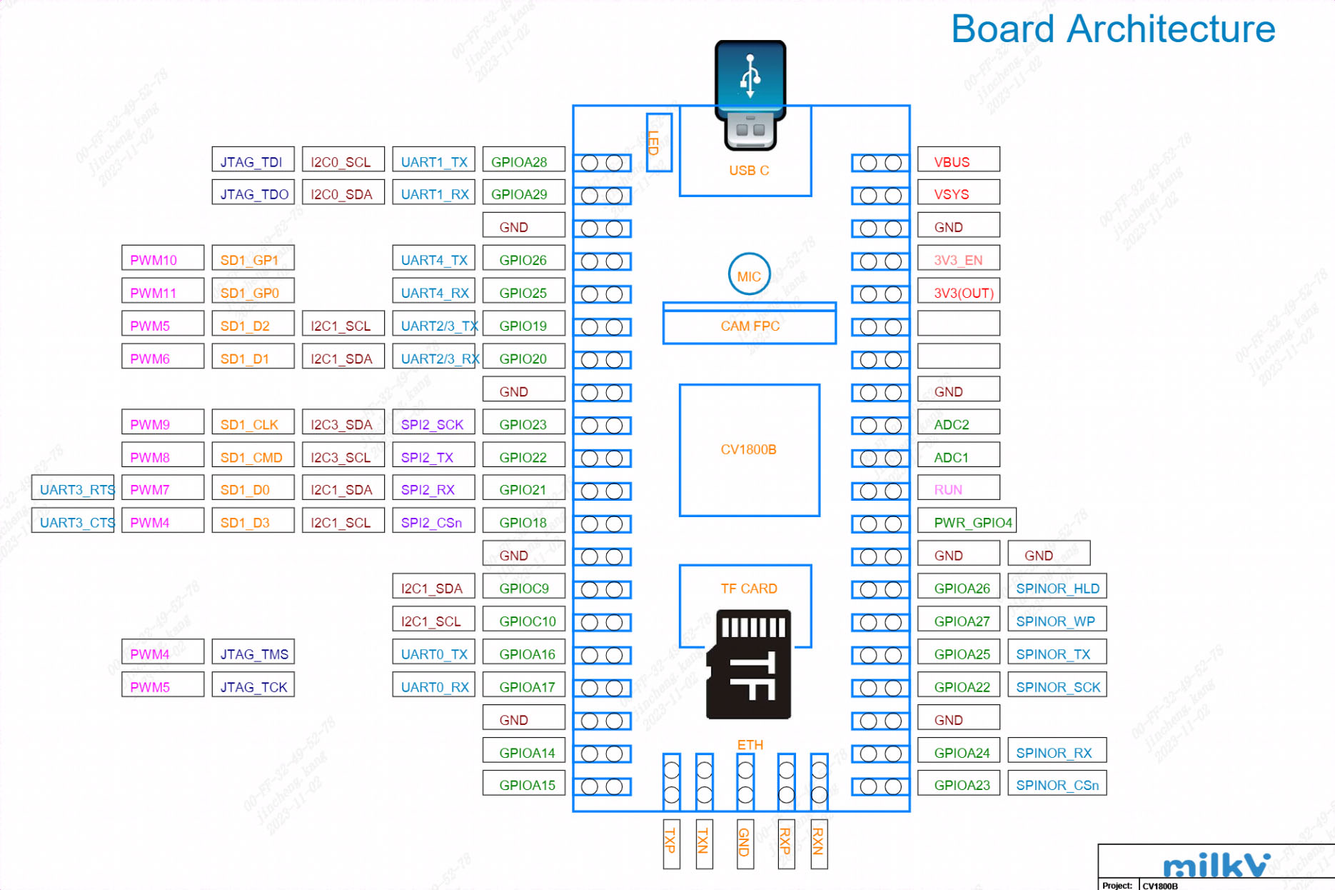
Hardware Information
Duo development board pin
GitHub Link: https://github.com/milkv-duo/duo-files/blob/main/duo/hardware/duo-schematic-v1.2.pdf
DHT22 Temperature and Humidity Sensor
dfrobotwiki Link: https://wiki.dfrobot.com.cn/\_SKU_SEN0137\_%E9%AB%98%E7%B2%BE%E5%BA%A6DHT22%E6%B8%A9%E6%B9%BF%E5%BA%A6%E4%BC%A0%E6%84%9F%E5%99%A8
The DHT22 Temperature and Humidity Sensor is a versatile and cost-effective sensor used for measuring environmental temperature and humidity. It is based on digital signal output, providing high-precision measurements with a temperature resolution of 0.1 degrees Celsius and humidity resolution of 0.1%. The sensor uses a capacitive humidity sensing element and a thermistor to measure humidity and temperature, respectively. The DHT22 sensor also has relatively low power consumption and can operate within a voltage range of 3.3V to 5V, making it suitable for battery-powered projects. Additionally, the sensor offers long-term stability and high reliability, making it an ideal choice for various applications, including HVAC systems, weather stations, and indoor air quality monitoring systems.
ensor Module
The DHT22 module has a total of 3 pins, while the DHT22 bare sensor has 4 pins. When considering the module with three pins, two are power pins, and one is the data pin. For the 4-pin sensor, the additional pin is an NC (No Connection) pin with no specific function. The pinout for both the module and the sensor is as follows:

- DATA: Data pin for 1-Wire communication.
- GND: Ground pin for the module.
- VCC: Power pin for the module.
- Not Used: This pin is not used in this sensor.
HT22 Sensor Module Component Markings
Apart from the sensor, the DHT22 module on the PCB includes only two components: a pull-up resistor and a decoupling capacitor. The component markings for the DHT22 module are as follows.

DHT22 Module Circuit Diagram
The complete schematic diagram of the DHT22 Temperature and Humidity Sensor module is shown in the diagram below.

The schematic diagram of the DHT22 module is as shown above. As mentioned earlier, the board has only a few components. The VCC and GND pins are directly connected to the DHT22 sensor, and the pull-up resistor is connected to the DATA pin. Tantalum and multi-layer capacitors provide sufficient filtering. In some PCBs, you may find an LED indicator as a power indicator, but for most circuit boards, the LED is not present.
Common Questions About DHT22 Sensor Module
Q: In simple terms, what is DHT22?
A: DHT22 is a more expensive version of the DHT11 sensor with better specifications. Its temperature measurement range is -40 to +125 degrees Celsius with an accuracy of ±0.5 degrees, while the DHT11 has a temperature range of 0 to 50 degrees Celsius with an accuracy of ±2 degrees.
Q: Is DHT22 analog or digital?
A: DHT-22 (also known as AM2302) is a digital output relative humidity and temperature sensor.
Q: Is DHT22 waterproof?
A: No, it is not waterproof.
Q: What is the sampling rate of the DHT11 sensor?
A: The sampling rate of the DHT22 is 1Hz.
Q: What protocol does DHT22 use?
A: The DHT22 sensor uses a proprietary single-wire communication protocol that sends and receives data through timed pulses.
How does DHT22 work?
If you are using an original DHT22 sensor, it contains an NTC thermistor and a sensor module. However, most sensors available in the market are non-original parts and contain a small sensor, as shown in the image below.

The humidity sensing element consists of a moisture-absorbing substrate sandwiched between two electrodes. As the substrate absorbs moisture, the resistance between the two electrodes decreases. The resistance change between the electrodes is proportional to the relative humidity. Higher relative humidity decreases the resistance between the electrodes, while lower relative humidity increases the resistance. This resistance change is measured by the onboard MCU's ADC and used to calculate relative humidity.

Each DHT22 component undergoes rigorous calibration in the laboratory, with extremely accurate humidity calibration. Calibration coefficients are stored as programs in OTP memory for use in the sensor's internal signal detection process.
DHT22 Single-Wire Communication Protocol
A single-wire communication protocol is used to communicate with the DHT22 and the microcontroller. Data sampling takes approximately 4 milliseconds to complete. The data consists of both decimal and integer parts and totals 40 bits in length, in MSB format. The data format is as follows: 8-bit integer RH data + 8-bit decimal RH data + 8-bit integer T data + 8-bit decimal T data + 8-bit checksum. If the data transmission is correct, the checksum should be the last 8 bits of "8-bit integer RH data + 8-bit decimal RH data + 8-bit integer T data + 8-bit decimal T data."
When the MCU sends the start signal, the DHT changes from low-power mode to running mode and dumps all 40 bits of data to the microcontroller. The microcontroller reads the data and calculates temperature and humidity based on the binary data.

The image above shows how data communication works with the microcontroller and DHT22.
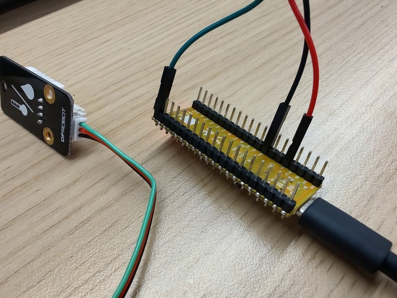
Connecting to the Development Board
DHT22: Red wire to 3V3 (OUT), black wire to ground, green wire to GPIOA15.
The circuit diagram is as follows: The black circle represents the DHT22.
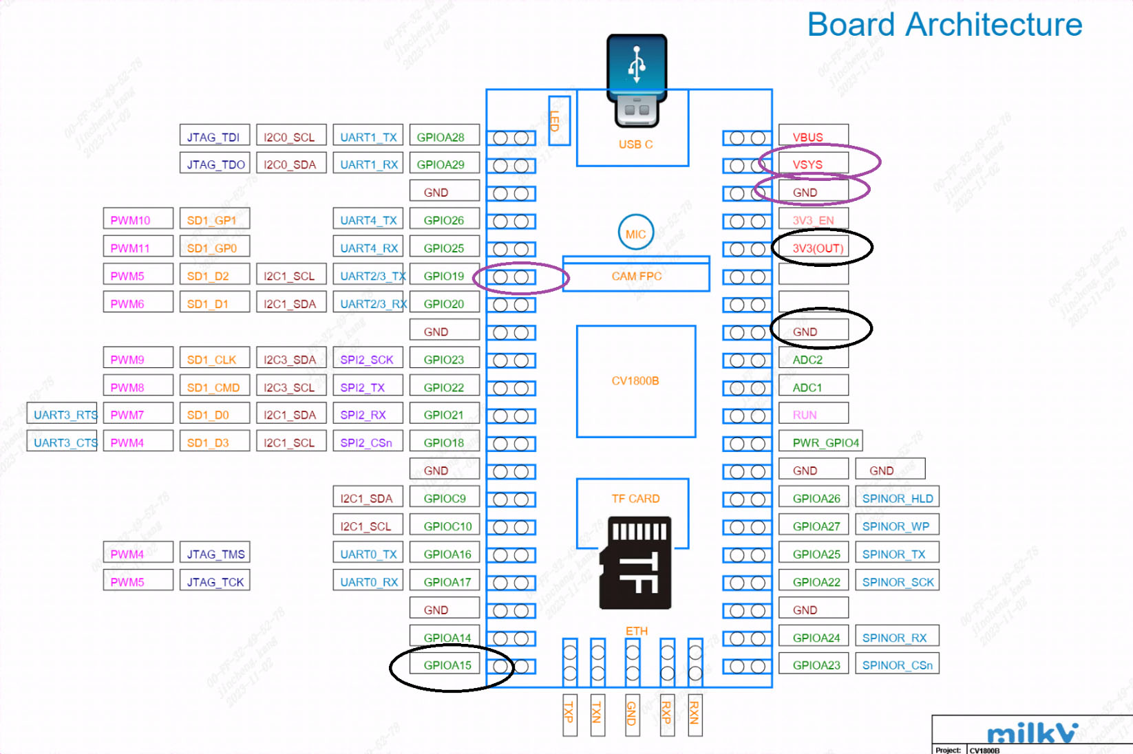
DHT22 should be connected as follows:
Example Code:
GitHub link: https://github.com/milkv-duo/duo-examples
dht22.c:
// Ref: https://github.com/technion/lol_dht22/blob/master/dht22.c
#include <stdio.h>
#include <stdlib.h>
#include <stdint.h>
#include <unistd.h>
#include <wiringx.h>
#define MAXTIMINGS 85
static int DHTPIN = 15;
static int dht22_dat[5] = {0, 0, 0, 0, 0};
static uint8_t sizecvt(const int read)
{
    /* digitalRead() and friends from wiringpi are defined as returning a value
    < 256. However, they are returned as int() types. This is a safety function */

    if (read > 255 || read < 0)
    {
        printf("Invalid data from wiringPi library\n");
        exit(EXIT_FAILURE);
    }
    return (uint8_t)read;
}

static int read_dht22_dat()
{
    uint8_t laststate = HIGH;
    uint8_t counter = 0;
    uint8_t j = 0, i;

    dht22_dat[0] = dht22_dat[1] = dht22_dat[2] = dht22_dat[3] = dht22_dat[4] = 0;

    // pull pin down for 18 milliseconds
    pinMode(DHTPIN, PINMODE_OUTPUT);
    digitalWrite(DHTPIN, HIGH);
    // delay(500);
    delayMicroseconds(500000);
    digitalWrite(DHTPIN, LOW);
    // delay(20);
    delayMicroseconds(20000);
    // prepare to read the pin
    pinMode(DHTPIN, PINMODE_INPUT);

    // detect change and read data
    for (i = 0; i < MAXTIMINGS; i++)
    {
        counter = 0;
        while (sizecvt(digitalRead(DHTPIN)) == laststate)
        {
            counter++;
            delayMicroseconds(2);
            if (counter == 255)
            {
                break;
            }
        }
        laststate = sizecvt(digitalRead(DHTPIN));

        if (counter == 255)
            break;

        // ignore first 3 transitions
        if ((i >= 4) && (i % 2 == 0))
        {
            // shove each bit into the storage bytes
            dht22_dat[j / 8] <<= 1;
            if (counter > 16)
                dht22_dat[j / 8] |= 1;
            j++;
        }
    }

    // check we read 40 bits (8bit x 5 ) + verify checksum in the last byte
    // print it out if data is good
    if ((j >= 40) &&
        (dht22_dat[4] == ((dht22_dat[0] + dht22_dat[1] + dht22_dat[2] + dht22_dat[3]) & 0xFF)))
    {
        float t, h;
        h = (float)dht22_dat[0] * 256 + (float)dht22_dat[1];
        h /= 10;
        t = (float)(dht22_dat[2] & 0x7F) * 256 + (float)dht22_dat[3];
        t /= 10.0;
        if ((dht22_dat[2] & 0x80) != 0)
            t *= -1;
        printf("Humidity = %.2f %% Temperature = %.2f *C \n", h, t);
        return 1;
    }
    else
    {
        printf("Data not good, skip\n");
        return 0;
    }
}

int main()
{
    // Duo:     milkv_duo
    // Duo256M: milkv_duo256m
    // DuoS:    milkv_duos
    if (wiringXSetup("milkv_duo", NULL) == -1)
    {
        wiringXGC();
        return -1;
    }

    if (wiringXValidGPIO(DHTPIN) != 0)
    {
        printf("Invalid GPIO %d\n", DHTPIN);
    }

    while (1)
    {
        read_dht22_dat();
        delayMicroseconds(1500000);
    }

    return 0;
}
Makefile:
TARGET=dht22

ifeq (,$(TOOLCHAIN_PREFIX))
$(error TOOLCHAIN_PREFIX is not set)
endif

ifeq (,$(CFLAGS))
$(error CFLAGS is not set)
endif

ifeq (,$(LDFLAGS))
$(error LDFLAGS is not set)
endif

CC = $(TOOLCHAIN_PREFIX)gcc
CFLAGS += -I$(SYSROOT)/usr/include
LDFLAGS += -L$(SYSROOT)/lib
LDFLAGS += -L$(SYSROOT)/usr/lib
LDFLAGS += -lwiringx

SOURCE = $(wildcard *.c)
OBJS = $(patsubst %.c,%.o,$(SOURCE))

$(TARGET): $(OBJS)
	$(CC) -o $@ $(OBJS) $(LDFLAGS)

%.o: %.c
	$(CC) $(CFLAGS) -o $@ -c $<

.PHONY: clean
clean:
	@rm *.o -rf
	@rm $(OBJS) -rf
	@rm $(TARGET)
Build environment on Ubuntu20.04
You can also use Ubuntu installed in a virtual machine, Ubuntu installed via WSL on Windows, or Ubuntu-based systems using Docker.
-
Install the tools that compile dependencies.
sudo apt-get install wget git make -
Get example source code
git clone https://github.com/milkv-duo/duo-examples.git -
Prepare compilation environment
cd duo-examples
source envsetup.sh
The first time you source it, the required SDK package will be automatically downloaded, which is approximately 180MB in size. Once downloaded, it will be automatically extracted to the
duo-examplesdirectory with the nameduo-sdk. When source it next time, if the directory already exists, it will not be downloaded again. -
Compile testing
Take hello-world as an example, enter the hello-world directory and execute make
cd hello-world
make
After the compilation is successful, send the generated
helloworldexecutable program to the Duo device through the network port or the RNDIS network. For example, the RNDIS method supported by the default firmware, Duo’s IP is 192.168.42.1, the user name isroot, and the password ismilkvscp helloworld [email protected]:/root/After sending successfully, run ./helloworld in the terminal logged in via ssh or serial port, and it will print
Hello, World![root@milkv]~# ./helloworld
Hello, World!At this point, our compilation and development environment is ready for use.
Operation Procedure

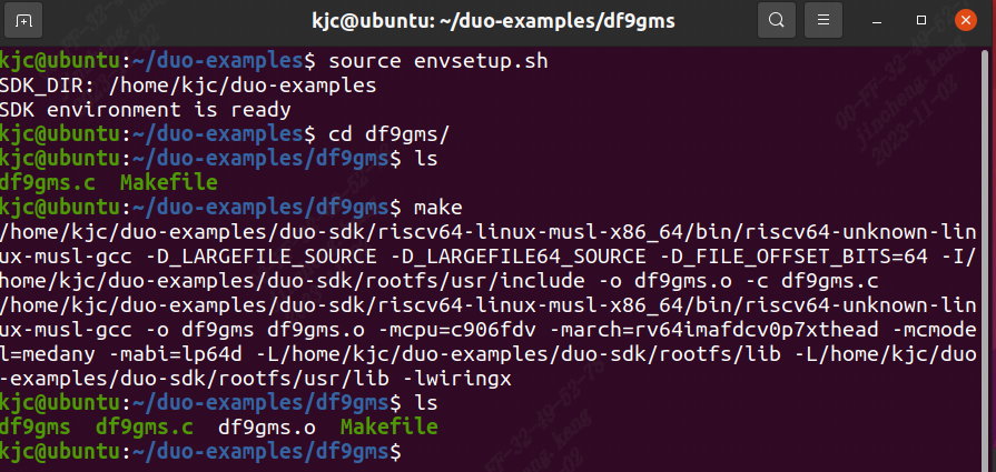
Next, compile it. Taking dht22 as an example, enter the directory of the example and simply execute make
cd dht22
make it
Make an error report and source it. After compiling successfully, you will get the df9gms executable program. As shown in the figure below.

Then upload df9gms to the root path of the development board, and enter ./dht22 to run it. The screenshot of successful running is shown below

DF9GMS 180°
Hardware Information
Duo development board pin
GitHub:https://github.com/milkv-duo/duo-files/blob/main/duo/hardware/duo-schematic-v1.2.pdf
DF9GMS 180°
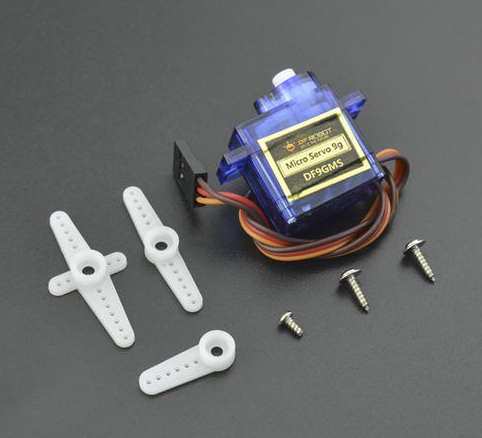
Micro Servo DF9GMS from DFRobot, this servo features a high-strength ABS transparent case with internal high-precision nylon gear set, precision control circuit and high-end lightweight hollow cup motor, resulting in a weight of only 9g for this mini servo, while the output torque reaches an amazing 1.6kg/cm.
Technical Specifications:
Operating Voltage: 4.8V
Torque: 1.6kg/cm (4.8V)
Speed: 0.14 seconds/60 degrees (4.8V)
Operating Temperature: -30 to +60 degrees Celsius
Deadband Width: 0.5 milliseconds
Physical Size: 23x12.2x29mm
Weight: 9g
Composition and Operating Principle of DF9GMS Micro Servo

Connection Diagram:
• Hardware
o 1 x Arduino UNO control board
o 1 x DF9GMS micro servo
o Several Dupont wires
o Gray - GND, red - VCC, yellow - signal line

connected to the development board
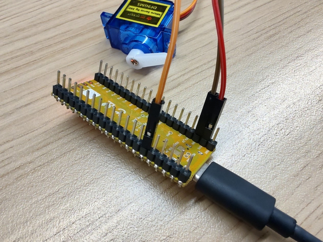
DF9GMS: red wire connected to VSYS, brown wire connected to ground, orange wire connected to GPIO19.
Circuit diagram shown below: purple circle represents DF9GMS.
DF9GMS should be connected as follows:
Example Code:
GitHub link: https://github.com/milkv-duo/duo-examples
df9gms.c:
#include <stdio.h>
#include <unistd.h>
#include <wiringx.h>
/*
Duo
------------------------------------------
PWM operation at a fixed frequency clock of 100MHz, writing Period in units of nanoseconds.
	DF9GMS 360-degree PWM Duty Cycle
	------------------------------------------
	0.4ms - 1.4ms CW deceleration
	1.5ms Stop
	1.6ms - 3ms CCW acceleration
*/
static int PWM_PIN = 4; // PWM5@GP4

int main()
{
    long i;

    // Duo:     milkv_duo
    // Duo256M: milkv_duo256m
    // DuoS:    milkv_duos
    if(wiringXSetup("milkv_duo", NULL) == -1) {
        wiringXGC();
        return -1;
    }

    wiringXPWMSetPeriod(PWM_PIN, 20000000);  // 20ms
    wiringXPWMSetDuty(PWM_PIN, 1500000);     // 1.5ms stop
    wiringXPWMSetPolarity(PWM_PIN, 0);       // 0-normal, 1-inversed
    wiringXPWMEnable(PWM_PIN, 1);            // 1-enable, 0-disable

    delayMicroseconds(1000000); // 1s

    for (i = 10000; i< 3000000; i += 10000) // 10 us
    {
        wiringXPWMSetDuty(PWM_PIN, i);
        printf("Duty: %ld\n", i);
        delayMicroseconds(50000); // 50ms
    }

    wiringXPWMSetDuty(PWM_PIN, 1500000);    // 1.5ms stop

    return 0;
}
Makefile:
TARGET=df9gms

ifeq (,$(TOOLCHAIN_PREFIX))
$(error TOOLCHAIN_PREFIX is not set)
endif

ifeq (,$(CFLAGS))
$(error CFLAGS is not set)
endif

ifeq (,$(LDFLAGS))
$(error LDFLAGS is not set)
endif

CC = $(TOOLCHAIN_PREFIX)gcc

CFLAGS += -I$(SYSROOT)/usr/include

LDFLAGS += -L$(SYSROOT)/lib
LDFLAGS += -L$(SYSROOT)/usr/lib
LDFLAGS += -lwiringx

SOURCE = $(wildcard *.c)
OBJS = $(patsubst %.c,%.o,$(SOURCE))

$(TARGET): $(OBJS)
	$(CC) -o $@ $(OBJS) $(LDFLAGS)

%.o: %.c
	$(CC) $(CFLAGS) -o $@ -c $<

.PHONY: clean
clean:
	@rm *.o -rf
	@rm $(OBJS) -rf
	@rm $(TARGET)
Build environment on Ubuntu20.04
You can also use Ubuntu installed in a virtual machine, Ubuntu installed via WSL on Windows, or Ubuntu-based systems using Docker.
-
Install the tools that compile dependencies.
sudo apt-get install wget git make -
Get example source code
git clone https://github.com/milkv-duo/duo-examples.git -
Prepare compilation environment
cd duo-examples
source envsetup.sh
The first time you source it, the required SDK package will be automatically downloaded, which is approximately 180MB in size. Once downloaded, it will be automatically extracted to the
duo-examplesdirectory with the nameduo-sdk. When source it next time, if the directory already exists, it will not be downloaded again. -
Compile testing
Take hello-world as an example, enter the hello-world directory and execute make
cd hello-world
make
After the compilation is successful, send the generated
helloworldexecutable program to the Duo device through the network port or the RNDIS network. For example, the RNDIS method supported by the default firmware, Duo’s IP is 192.168.42.1, the user name isroot, and the password ismilkvscp helloworld [email protected]:/root/After sending successfully, run ./helloworld in the terminal logged in via ssh or serial port, and it will print
Hello, World![root@milkv]~# ./helloworld
Hello, World!At this point, our compilation and development environment is ready for use.
Operation Procedure
Next, compile it. Taking df9gms as an example, enter the directory of the example and simply execute make
cd df9gms
make it
Make an error report and source it. After compiling successfully, you will get the df9gms executable program. As shown in the figure below.
Then upload df9gms to the root path of the development board, and enter ./df9gms to run it. The screenshot of successful running is shown below